- A passable GWR Passenger Brake Van to Diagram V5 -
by Tony Richards

Credible model railways need variety to be convincing and, all too often, GWR layouts contain the same old coaching stock regardless of whether it is a Branch, Suburban or Express set-up. Centenary, Hawksworth and B-Set vehicles all have their place but it’s good to ring the changes with different stock to add interest, and it needn’t be difficult either.
This article shows how to construct a rarely modelled item, a four-wheel Passenger Brake Van [very approximately to Diagram V5]. The donor parts are cheap and only basic modelling tools and materials are needed, along with paint and transfers. You will also need [Hornby] metal coach wheels and brass bearing cups for them to run in.
For the conversion you will require pair of Triang Clerestory Brake coaches [any livery will do], a Ratio four-wheel Composite coach chassis, the roof from the same Ratio kit and various bits of Perspex and wire. The Triang coaches, with patience, can be sourced very cheaply via eBay, as can the Ratio kit.
Start by completely disassembling the Triang coaches. The roofs are screwed from below and also fit into slots at each end of the coach. Cut away the bogies and the simple underframe. You should aim to be left with just the basic bodies.
Next, with a fine-toothed razor saw, slice the bodies in half carefully, ensuring that the cuts are square and no damage is done to the moulded panelling. Study the photograph below to see what I mean and note where the cuts should be made on either coach side.
NB: because the ducket is slightly wider than the door on the opposite side, the cut will need to be made at a slight angle to avoid damaging the door. Examining the actual bodies will make this clearer.
Both bodies have been cut through immediately to the right of the look-out ducket and the side of the ducket provides a useful edge against which to cut . The left-hand half shows this clearly. The right-hand half has been reversed to join the left to create the coach body. There will be a need to file and sand the cuts on both sides very carefully to ensure that both halves fit together snugly and squarely. This is really important but it is not difficult: go at it slowly, checking the fit regularly as you proceed.
The photo below shows both coach halves butted together once the cuts had been adjusted. The slight difference in height was caused by an uneven base for the photograph.
With the razor saw, now remove the steps board from the bottom of the coach sides. Photo one shows the left side with the step removed whilst the right remains in place. The buffer beams at each end need removing also. Sand or file once done to ensure that the bottom of the coach is completely flat and square. The second photo shows what the finished operation should look like.
Once the above operations have been completed satisfactorily, the two halves of the coach body may be joined together. This is best achieved by first reinforcing the joint at inner floor level by glueing a thick piece of plastic card across the floor of both halves. Once that has cured, the sides may be glued with Mekpak or an equivalent liquid solvent, applied from the inside with a fine brush. Undertake this operation on a completely flat surface [a sheet of glass is ideal] to ensure a square bond. Set the body aside now, to cure fully, before attempting any other work.
Next, spray the body with grey primer. This will show up any imperfections in your work and identify where filler, or other remedial work, is required to pack out the joints or repair the sides. The next photo shows how filler [Milliput] has been applied to one of the lower sides to fill a joint and so improve the appearance of the model. The small gap at the top was left unfilled as paint would deal with that. Once any filler used has cured, prime the body again.
When satisfied with the result, the body may be painted [aerosols are fine and the masking is straightforward if you opt for a simple livery] and then set aside for the next operation – building the sides of the chassis. Note however that painting the body before attaching it to the chassis will save a great deal of later effort and masking.
The coach chassis should be constructed as per the instructions in the Ratio kit. This is quite straightforward although the floor provided in the kit was discarded and once made up, the sole bars and axle units were glued directly onto the underside of the coach body, butting against moulded ridge that runs longitudinally down each side of the body. The plastic tie bars [the thin bars between the axle boxes] were removed completely and replaced with thin brass rod. The originals are extremely vulnerable and break easily. Repair is almost impossible and replacing them with brass rod is an easy and more permanent option. Simply file a longitudinal ‘V’ into the bottom of each ‘W’ iron and superglue the rod into place. The three vertical hangers on each side can be super-glued to the rod as well. The left hand photo below shows this.
Do not use the plastic wheels supplied with the Ratio kit: I’d suggest that you fit Hornby [metal] coach disks and glue Slater’s brass bearing cups into the axle holes to ensure free running wheel sets.
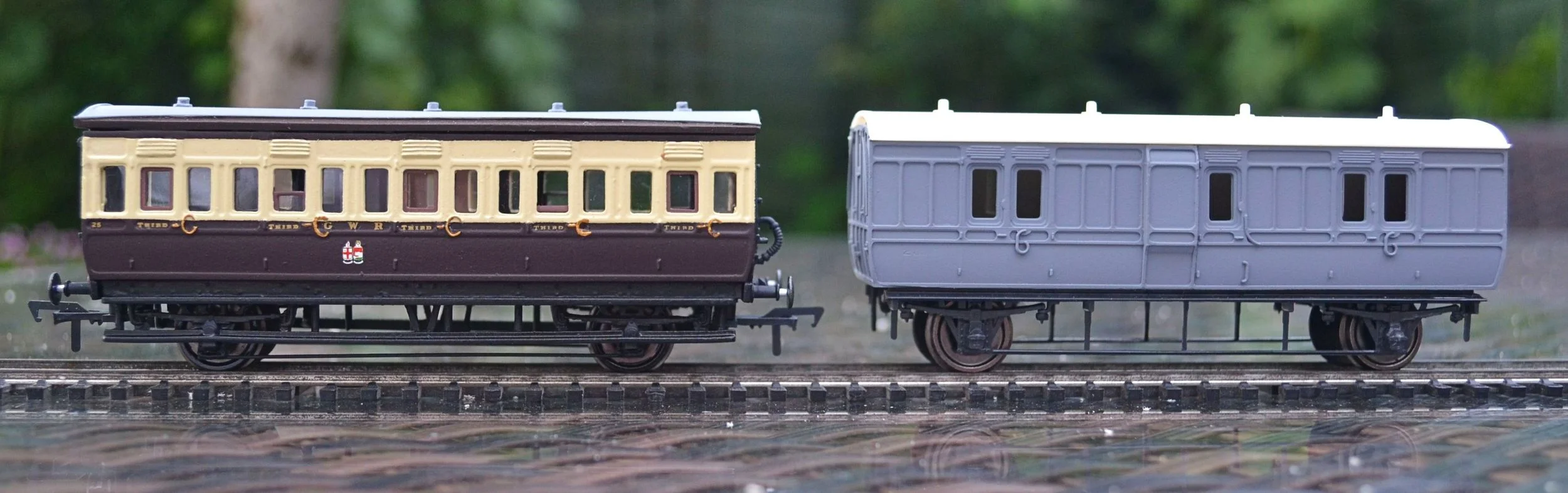
The next three photos show the chassis in various stages of completion: it is finished on the right. In the centre photo, the coach is being checked for ride height against another vehicle [in this case, a K’s white-metal four-wheeler]. Note that no buffer beams have been fitted at this time: the chassis is slightly shorter than the body to allow for buffer beams to be attached – and fill out the gap at each end – later.
The next operation is optional but I always like to spray chassis with grey primer if I have fitted metal parts. This will help the final spray of matt black to adhere properly.

The only really tricky part of this build comes next. The photos below show that the Ratio coach roof has a completely different profile to the Triang coach ends: there is a significant gap and this needs addressing if the roof is to fit. The roof is also a fraction too short: if your cutting and joining have been accurate, the coach body will be exactly the same length as the roof. There should be a slight overhang however, with the roof being perhaps 2 mm longer than the body. This can all be remedied but it is fiddley.

To deal with the roof length first, take some very thin 2mm plastic strip and glue it over each end of the roof. Aim for a 1mm overhang at each end and once glued leave it to cure fully. Once hardened, glue some of the same strip under the overhang. Once that has cured, sand it back carefully until both it and the original overhang are the same length. That will deal with the roof length issue. The penultimate photo below shows how this should look.
The roof / ends profile can be resolved by glueing the same plastic strip in several layers to the top of the coach ends and the underside of the roof [but not extending to the overhang] and then sanding each back until a satisfactory join is achieved. Any slight gaps can be dressed with filler once the roof has been glued to the body. This is a trial and error method and regular dry runs will be necessary to establish how much further sanding is required and where it should take place. It sounds far harder than it is in practice but is – as I said – fiddley. Patience will repay in spades here.
The photo below shows the above operation, but partially completed and a lot more dressing will be required to ensure a good fit. Note that a buffer beam – and buffers, etc. - have now been fitted to the chassis. These came from the ‘bits box’ but you could use the beam and buffing gear from the Ratio coach if you wished [simply cut what was required from the kit’s coach ends and glue to the chassis]. The coach ends will ultimately be sprayed black.
I fitted a more prominent rain strip to the roof at this stage. The photo below shows this, although note that the roof is still a dry fit only. A first coat of chocolate has been applied also. Note the improved roof overhang.
By this stage, and assuming that the livery details have been applied, the coach ends painted black and the chassis painted, there is very little left to do beyond glazing the model, adding glazing bars and fitting the roof. Glazing can be done in a number of ways: the easiest [and quickest] is by fixing perspex to the window openings from behind. As long as glue does not seep through onto the 'glass', this can look quite convincing. It is not flush however and the windows will appear inevitably deep-set. I opted for SouthEast Finecast flush glazing instead. The pack for Triang Clerestories is cheap, easy to apply and more convincing as it fills out the window space quite well. Glazing bars were made up from brass wire sprayed cream and glued to the inside walls over the windows.
The V5 PBV is an easy and satisfying project that would be well within the average modeller's skill-set. It provides a interesting and infrequently modelled subject, one which would run particularly well with Ratio or other 4-wheel coaches and would be at home on any branch or secondary line.
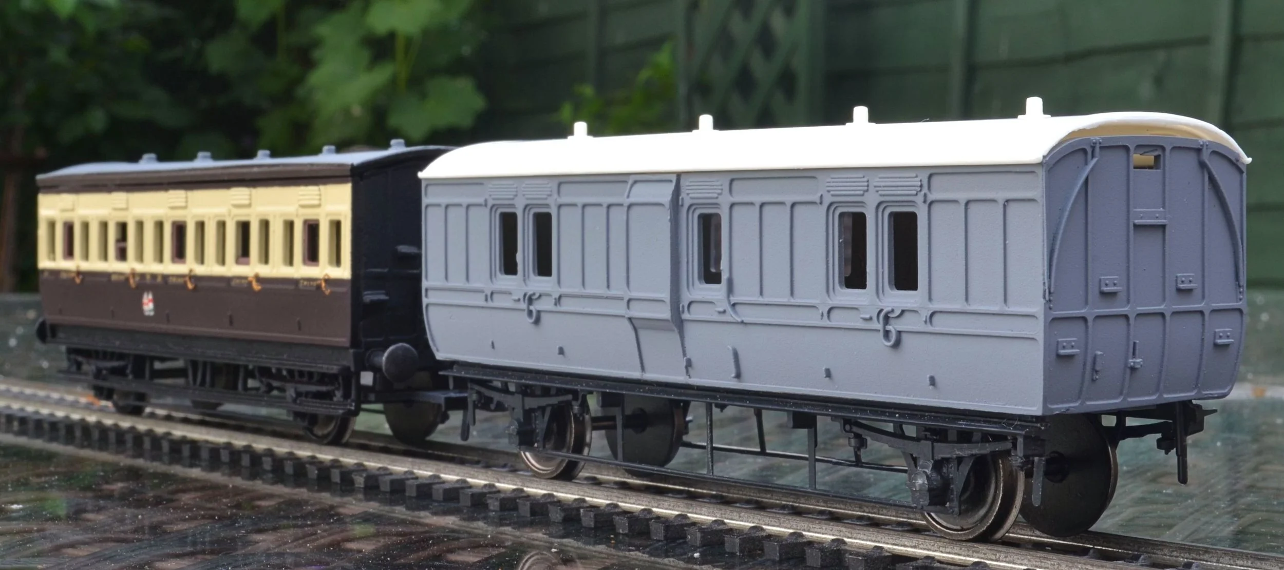
The final photo below shows the finished model painted in the GWR's 1927-1934 livery.