- Detailing Hornby's ancient open-cab Pannier -
by Tony Richards
CLICK ON ALL PHOTOS TO ENLARGE
First released by Hornby in 1980, the Victorian 2721 Class open-cab Pannier is still widely available although now with a more modern chassis and a far better paint job than when originally introduced. There's something quite delightful about open-cabbed tanks: they bring real period charm to a layout and, given their scarcity in r-t-r model form, if you want a GWR one then this has to be it [ignoring of course Hornby’s 0-4-0 ‘101’, that strange and better-avoided model of the unique Holden experimental oil-burner].
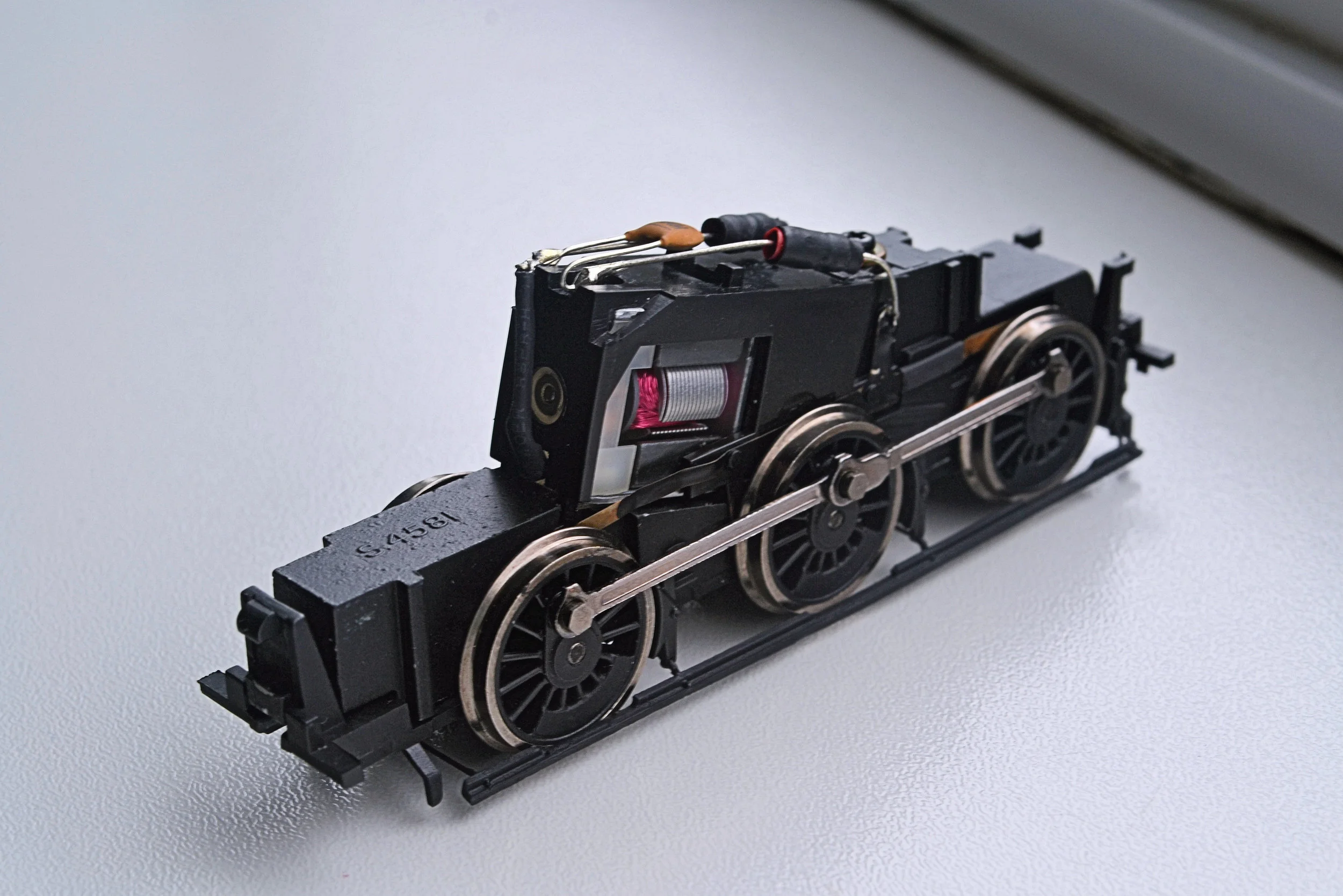
The photos below shows one of the earlier releases of the Class with the original XO4 chassis and unrealistically plated safety-valve bonnet.


I dragged my model out of its box to consider it further against drawings. I wanted to upgrade the tank so that it could run amongst more modern, better-detailed releases without shaming itself but my initial thoughts on first seeing a model I hadn't looked at for maybe five years were that it was too poor a representation to bother with. However, against the drawings, it is reasonably accurate and scales a mere 9" [3mm] too long - perhaps not too bad for 35+ year old r-t-r. It is just a little too high also [both of these faults are chassis-driven, the body being designed to fit the mechanism rather than vice-versa]. The body detail is actually not that bad but the chassis, even though improved, is sparse and clearly lets it down.
Unfortunately, photographs of the prototype are extremely uncommon: consequently, the position and nature of the detail parts to be added have had to be surmised from photographs of similar GWR tanks of the same period. I'm fairly confident that no absolute howlers will follow, although some compromise will inevitably be necessary. Given the nature of the donor model, they will pale into insignificance however.....
So, the plan in summary:
remove existing buffers and fit Dean pattern tapered ones in their place; fit lamp irons and smoke box dart;
construct and fit brake pull rods; replace safety valve bonnet; remove and re-site correctly the bunker unit;
add coal to bunker; fabricate irons for cab tarpaulin; paint and detail backhead; add crew;
add etched cab-side number plates [2745]; add fire iron hooks to rear; add pipes to the front sand boxes;
paint and letter; add fire iron tools and lamps; add spectacle frames; varnish.
….and hope that it’s all worthwhile !
Most of the above will be provided from the bits-box. Some parts will need to be ordered in however although I have limited them to etched number plates, replacement buffers and spectacle frames.
Whilst waiting for the ordered parts to arrive I made a start on the bunker, an assembly which conveniently clipped away from the main body and one which needed quite a bit of work to improve the detail. The clips were difficult to release on my model so I simply cut them away from underneath rather than risk damaging the buffer beam on the main body. The bunker unit will be glued back into place anyway.
This is the bunker on the donor model [a nice touch is the moulded furled tarpaulin at the roof edge]:
It was apparent before removal that on my model the bunker sat with a upward slope towards the front - see the photo above. This would need to be remedied. On removal it became clear that rough moulding on the underside of the bunker and the topside of the footplate was to blame. This was cleaned up with an emery board - better than a file for this sort of job as it has a much wider face and does not cut in so much. I then glued some very thin plastic strip to the underside of the bunker and sanded that in places to ensure complete and square contact all around. At the same time, I bent up and attached some fire-iron hooks from brass strip and repaired a very bent handrail on the bunker side. You'll see from the photo above two strange and shapeless pips at the edges of the rear face of the bunker. I think these must be Hornby's hopeless attempt to represent fire-iron hooks, they certainly could not be anything else. They went before their brass replacements were fitted. The left-hand photo below shows a dry fit after this work had been completed. You'll see the thin plastic buffer between the two parts of the body quite clearly and also a replacement floor to the actual bunker area [I removed the moulded coal and binned it so that real coal could be loaded later]. I have also removed the cab roof and the safety valve bonnet from the body proper.

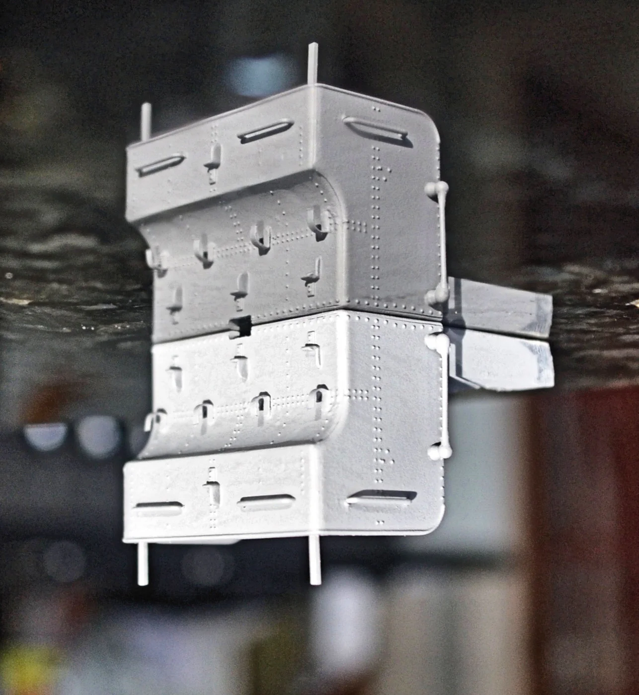
The right-hand photo above shows the bunker sub-assembly completed and in primer. The two rods sticking up at the back are for the cab tarpaulin to be attached too, they are rarely modelled. I'll thin them down a little in due course because they are a little over-scale.
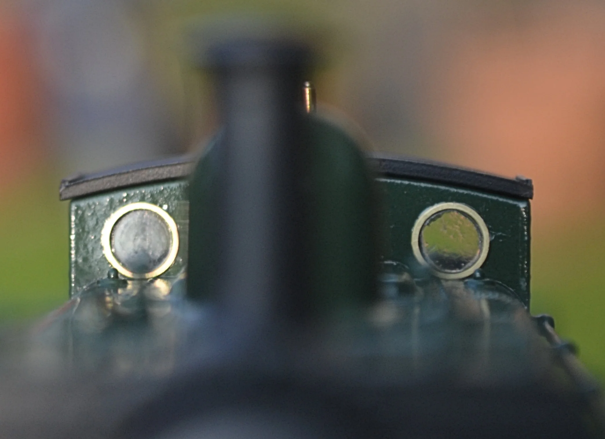
Oh, that photo may look a little odd. It is. I photographed it in quite strong sunlight and the focus settled on the reflection, not the model. I've simply inverted the picture to show the better image [the reflection] uppermost !
Turning next to the main part of the body, I removed the buffers from the front and rear buffer beams, shaved off the smoke-box door dart and refitted a more accurate safety-valve bonnet.
The buffers are not difficult to remove but real care must be exercised. The metal heads are an easy pull out, keep them if you want but I threw mine away as they are simply too generic to be of any use [to me anyway]. The buffer housings were then snipped off with some shears and the remaining square plates very carefully sliced and sanded flush to the beam itself. Replacement buffer units were then super-glued over the site of the original buffers and the model set aside to give time for the adhesive to fully cure.
This exercise inevitably damages some of the bolt-head detail on the buffer beam. This can be reinstated by gluing slivers of plastic rod in their place. Done carefully it is effective and a further photo will show this.
The smoke-box dart was carefully cut away with a scalpel and then the remaining scar sanded smooth. A hole was drilled centrally in the smoke-box door and a replacement brass dart glued into it. Again, time was allowed for the adhesive to cure fully so that handling would not dislodge it.
The next photos show a dry run with the main body parts and it's almost time for a final coat of primer. I find photos quite useful and their different perspective sometimes picks up what the Mk1 eyeball does not. In this case I've noticed that the front right buffer housing drops a little - that will be removed and the site sanded before it is refitted. As mentioned above, a number of bolt-heads were also cut away whilst the original buffers were being removed. These will be reinstated. Note that I managed to drill the uprights on the water tank fillers to accept handles. I must also shorten one of the smoke-box door handles.


You'll notice from the centre photo that I have also drilled out the bottom of each of the brake hangers to accept cross pieces and provide support for the external pull rods. I haven't yet decided how those will be constructed though.
The next photo shows the business end with a final coat of primer applied and buffer housing re-sited also. The bolt-heads are an improvement but maybe a little on the heavy side. I think that the next few coats of paint will subdue them however, so I'm not too worried. For each bolt-head successfully applied a good half-dozen pinged off into outer-space ! I must investigate the sheets of rivet / bolt-head transfers that can now be purchased, they will give an easier and more consistent finish.
The enlargement is a little cruel, digital photographs take no prisoners! The joint seam running across the top of the smoke-box / panniers will disappear almost completely when the final top coats of paint are applied. I've been giving that chimney some thought, too. It's pretty much the correct height but, as you can see, it has a slight flare at the base: it really should be parallel all the way up. Somebody does make a cast copper replacement and I thought about purchasing one. However, removing the existing one would almost inevitably damage the top of the smoke box and the rivet detail there is very fine. It'll stay put I think.
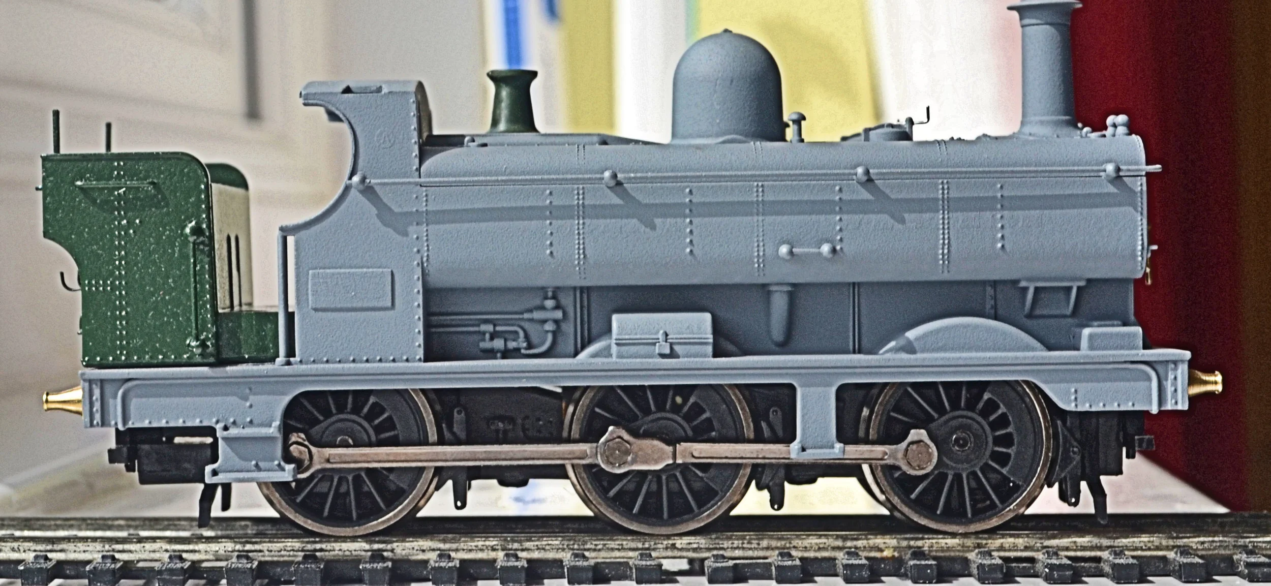
The next photo shows the business end again, in a first coat of green [the orange-peel finish will disappear under further coats of green], with the lamp irons and steam lance valve fitted [at 9 o'clock on the smoke-box front]. The lamp irons are in the correct positions but they are not of the correct pattern. The gauge of brass strip that I was using was so fine that whilst it would tolerate bending at 90 degrees it would not be twisted at 90 degrees. I suppose I could have bought some etched parts but there we are. This is a glaring error on a GWR loco but given the other deficiencies in the model created by Hornby it isn't exactly critical.
All is now ready for painting and livery detailing. The weather is changing however so spraying may be held of for a few days - we'll see.....
As mentioned earlier, one of the big problems in applying detail to this engine has been the virtual absence of any original photos on the web. I found just two, and they were not of much use. Even Volume One of Russell has no photos of the locos in this number series although there is a line drawing. So, locos with similar fittings, particularly the earlier ones in the group, have had to be relied upon.
Time now to put the body aside and give some thought to constructing the brake pull-rods, a prominent feature on the prototype and completely missing on the donor model.
After three hours of cutting and trimming, the brake pull-rods proved to be more than a little challenging. As you'll see below, each side needs three notches cut out to clear the swing of the coupling rods: it's the same for both the prototype and the model. The rods also need to be attached to the bottom of the brake hangers but, if simply attached there, they foul the coupling rods completely. This model was not designed with detailing in mind !
It was inevitable that I'd have to use plastic for this task but contrapting these out of plastic card was always going to be problematic. Brass sheet would have been far better, but I didn't have any thin enough and it would have required a bending jig too, something else I don't have [I can see a purchase though]. The main difficulty created by the use of plastic strip lies in the strength-v-scale thickness formula: inevitably, it has to be thicker than you'd like and as it also requires a lot of trimming, some warping will occur too, simply as a consequence of the thickness and profile of the scalpel blade. Then there's the problem of hanging the rods both convincingly and close enough to their correct location so that they neither foul the connecting rods nor the rail head.
The rods should not look like footboards either. This was a deliberate compromise to allow handling without breakage. Further, whilst the rods need to be strong enough to withstand inevitable accidental handling they should not be so thick that they look out of place and overscale. So, whatever I settle for will have to be representational rather than prototypical, which is never the place that I like to start from really.
I know, I know. It all sounds like excuses. But it genuinely was more difficult that it looks. Ironically however, they'll not get a second glance when running because everyone will expect them to be there anyway [which is quite helpful !]. For me, part of the right hand side is just a shade too close to the rail head and I can see a slight warp, too. But, painted matt black, they look infinitely better than they did earlier, so they'll stay. Good enough is good enough in this case and they can always be removed at a later date should I find a suitable and affordable brass etching.
The plastic used to make the pull-rods was 'Evergreen' strip, a 'T' section which had one of its horizontal arms trimmed off to produce an inverted 'L', into which notches were cut out to clear the swing of the connecting rods. The upright of the 'L' was then trimmed back to make it less deep and holes were drilled at the appropriate places so that the completed rod could be glued to cranked cross wires which had already been inserted into the brake hangers.

Progress is a little slower now. Spraying loco bodies is so much easier when the running plate can be separated from the main body itself. Single-piece models like this require a great deal of masking which is arduous frankly, dozens of slivers of tape to be attached and then carefully and quickly removed without touching the fresh paintwork. The time spent is worth it though. The tank body required six separate operations: the whole unit first painted in green [twice] and then masked up to be painted in black to the smoke box front, chimney and smoke box top, left side and right side. I was pleased that only a little touching in will be required now, all in the nooks and crannies under the tanks where flat masking wasn't possible. The back-head will be the next major painting task.
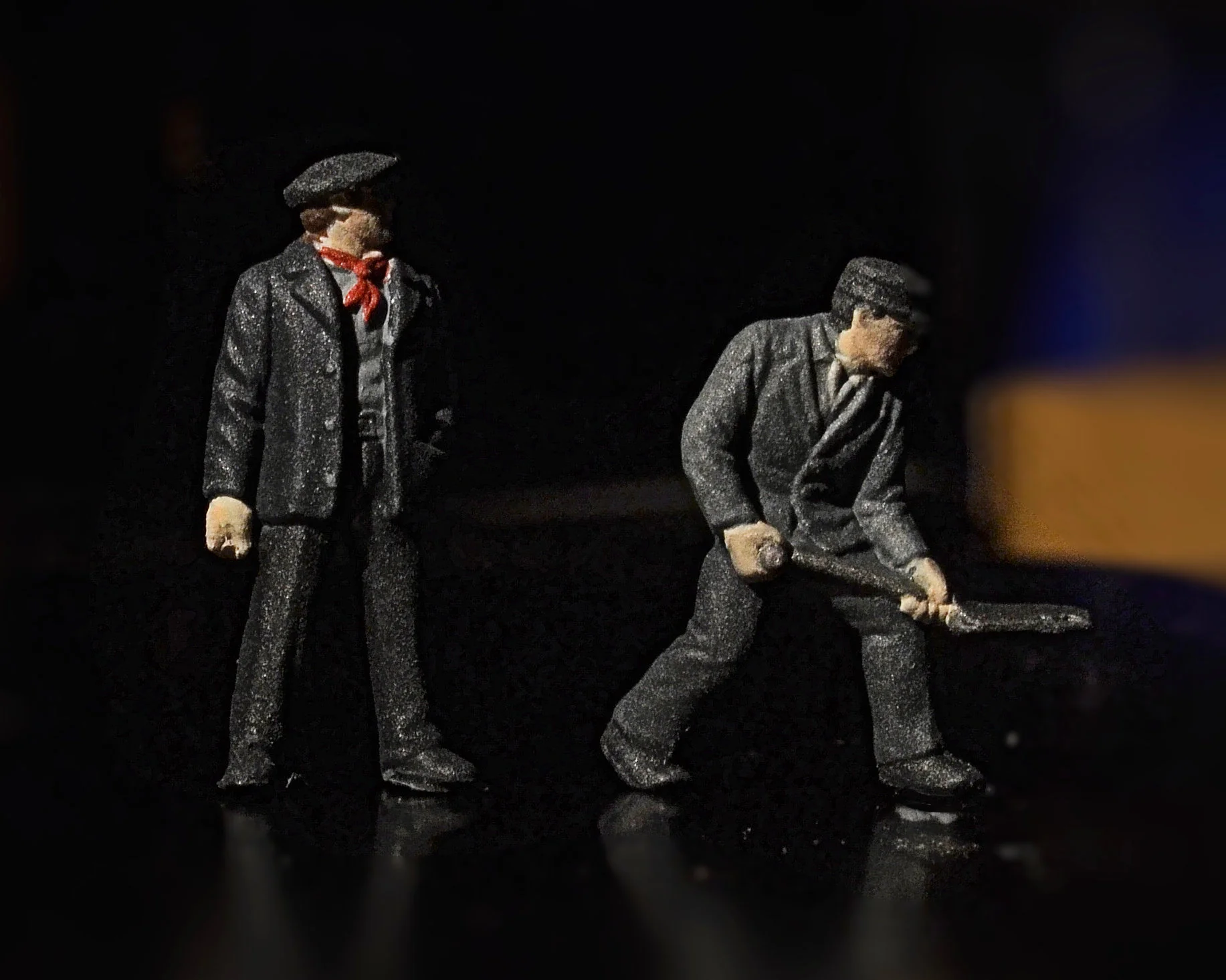
I've also painted the crew. I'm hugely dissatisfied with the availability of convincing loco figures - there's a market out there begging for variety. I've looked at white metal and pewter but, apart from the considerable cost of the better ones, so many look like Richard the Third or a band of Hobbits. Caricatures just don't work for me. And just look at this offering from Slater's too. Just what on earth are you supposed to do with them ?
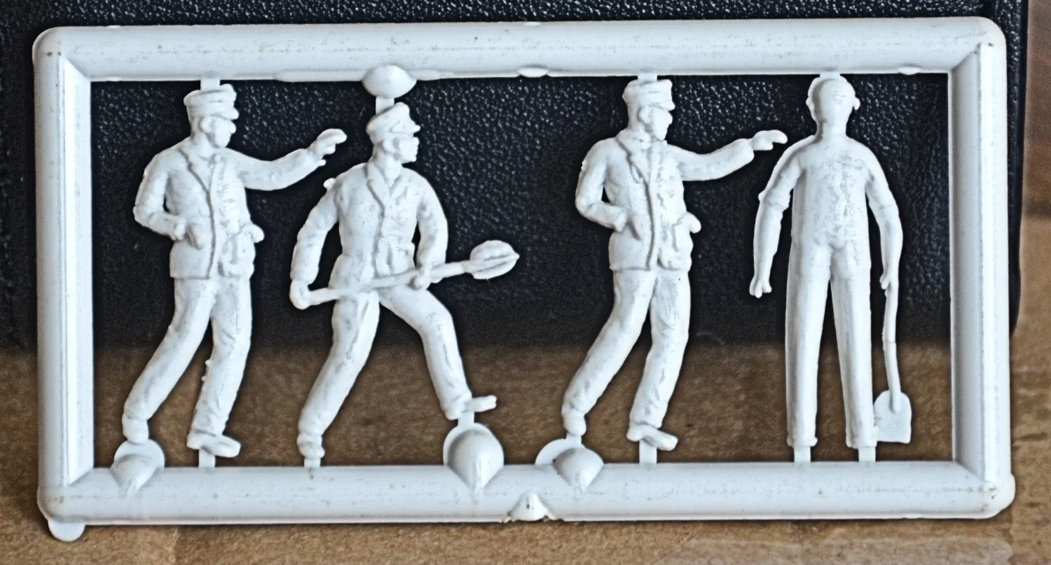
The two drivers are screaming 'oooooh Matron' and the firemen are equally useless. They are all very flat too, with absolutely no depth at all. Where would you put them ? How on earth could they be made to stand up ?
Whilst bits of the Hornby / Bachmann loco crew packs can be used, I rely generally on cannibalised Dapol permanent way figures - they are easy to slice up and with care arms can be swapped and heads shared. Frankenstein stuff, but it can be effective.
Painting is where it finally falls apart for me. The penny has finally dropped and I am going to have to invest in some really good, really fine brushes for figure painting [and use them only for that]. It's impossible to enhance poor detail with a toothbrush. I think I'll switch to acrylics too, rather than Humbrol enamels, for this task - the brushes will last longer and mistakes are easier to correct.
So, below is the very last set of enamel-painted crew. I tried to pick out the eyes and mouths convincingly but the depressions in the models just weren't deep enough to hold paint. They'll work well enough for the tank, but I'm looking forward to developing some skill in this aspect of modelling. By the way, I thought that the driver looked like he'd escaped from the SNCF, he has a distinctly French caste to him...

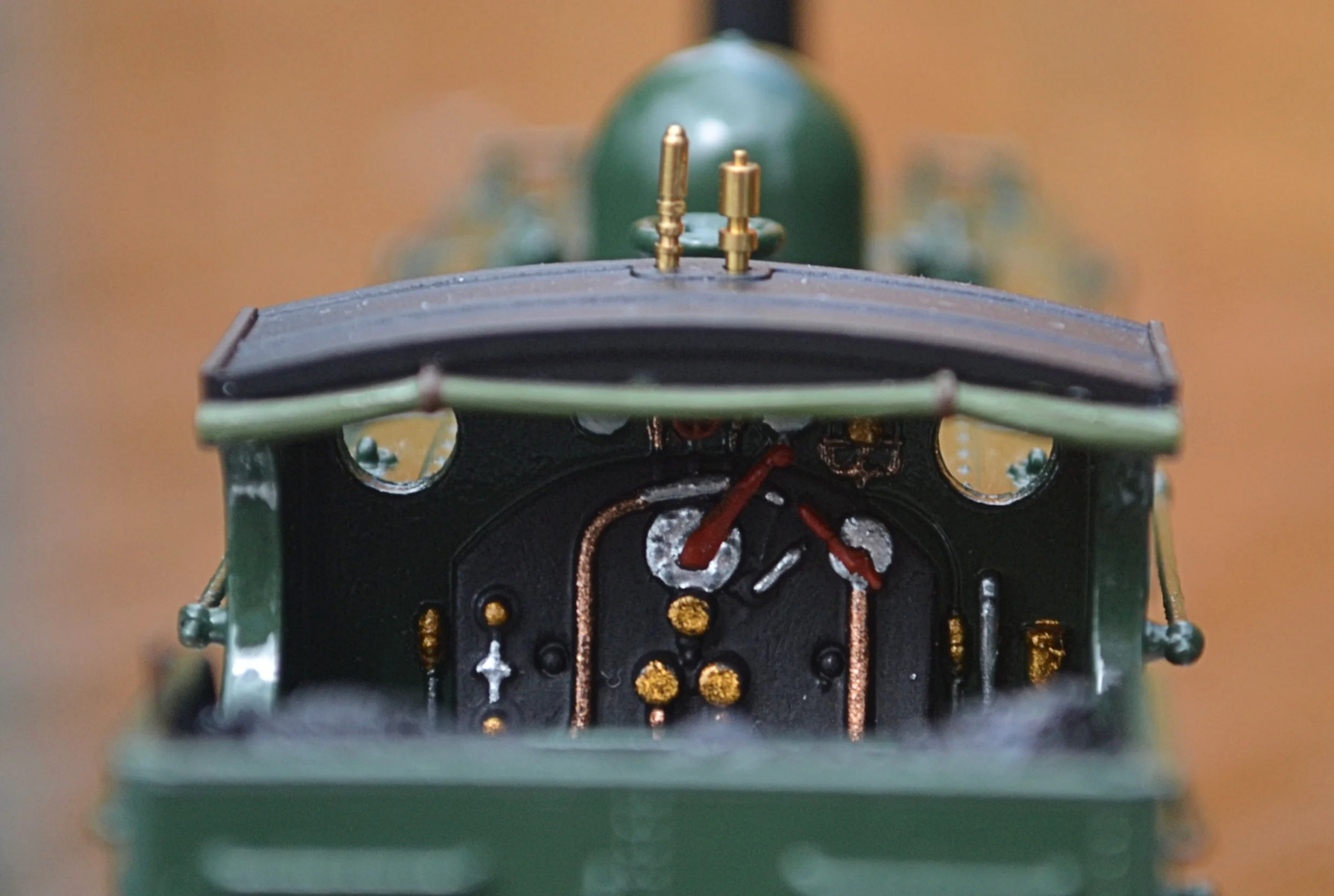
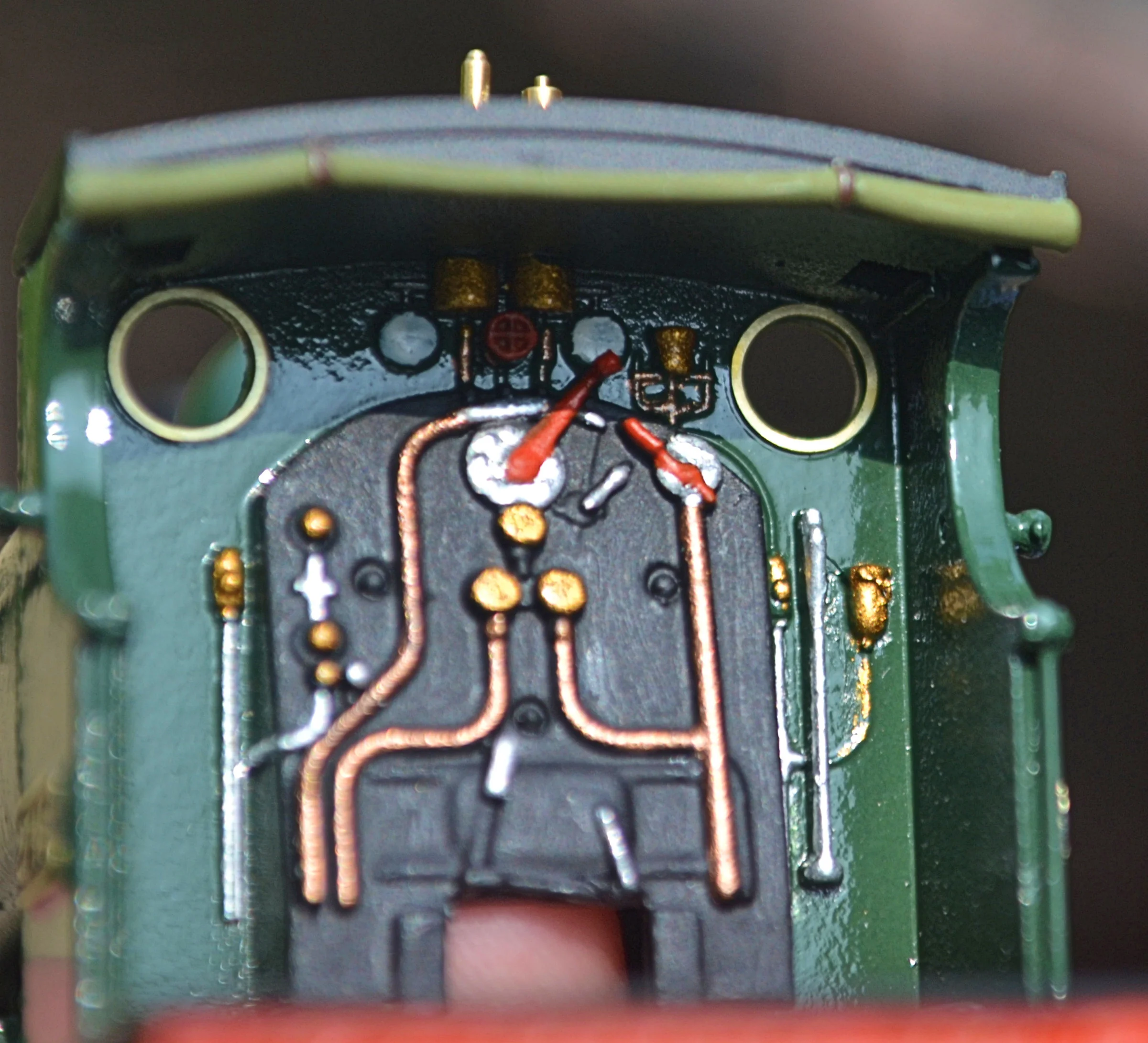
Left-hand photo below - probably the only time it's going to be seen in its entirety ! I really must invest in some finer brushes as the backhead pipework was done with a battered size 0 and it was a nightmare.There's still a wee bit of tiny pipework to do up by the gauges - that's the value of an enlarged photograph.
Right-hand photo below - it's a real shame that the backheads on these models are not detachable. The photo shows the backhead on the original early-80s release. The moulding is much crisper and more sharply defined. The left-hand photo shows three brass disks above the firebox. I knew that these were valve wheels even though they were simply flat mouldings. The right-hand photo shows them as originally moulded. They would have picked out beautifully in brass.


There's been a lot of activity but no posting on this for a while. Why ? A paint disaster: a well-learned lesson was forgotten and a damp day necessitated a complete respray - that's an awful lot of masking and doing it without braking off the lamp irons was an absolute pig. Never, ever spray paint on a day which is either very humid or very cold, it will almost certainly lead to fogging or misting.
And it's truly astonishing just how much extra weight the paint had added to the body. Anyway, the paint job is near complete now - just one or two bits of silver and brass to apply to the injectors and fire irons and, of course, lettering, numbers and spectacle plates. Add the crew and glue on the bunker and we're done.
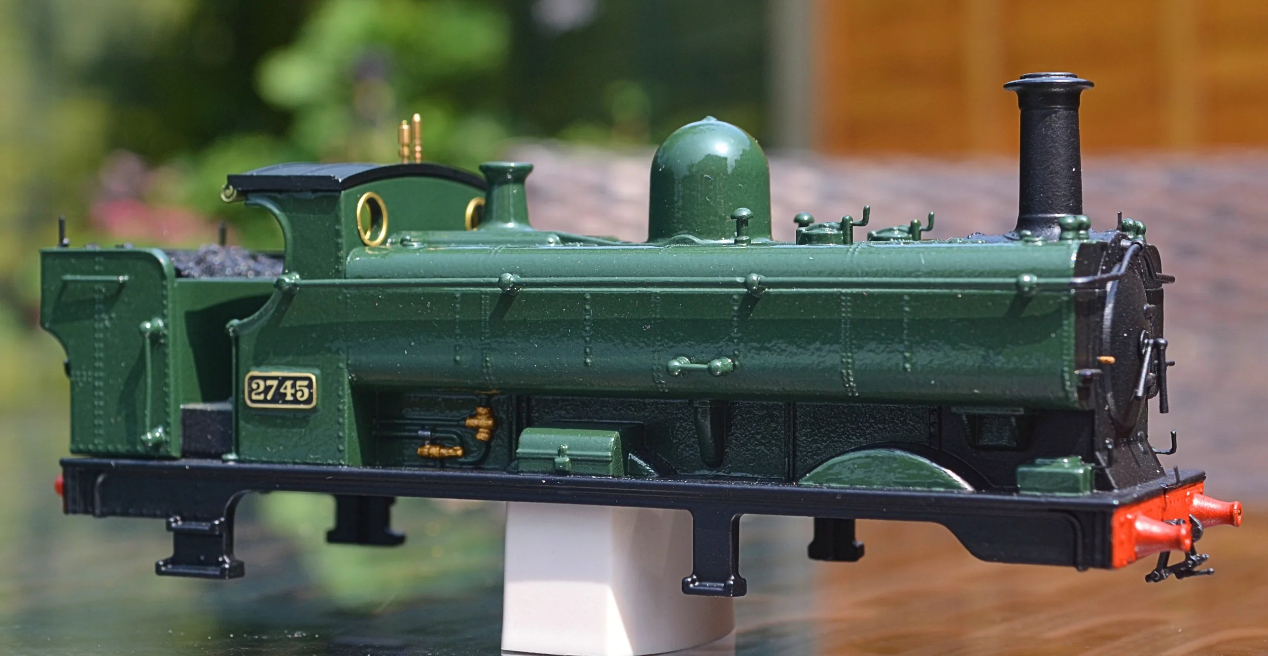
The photos below show that I've now gone for a glossy ex-works finish this time - it would have run like this for maybe a month or two, gradually getting oilier and grimey in spite of cleaning, and the Brunswick Green darkening towards a different shade altogether. The lettering will change also, I had planned for 'GWR' but now it will become 'Great Western', allowing it to run through a much longer time frame. I have also scribed some planking into the cab floor before painting it. It's an improvement. Real coal has been added and the irons for the tarpaulin have been changed for thinner, sturdier ones, too.
But, two things that I really should have done - and I'm absolutely kicking myself over this - are sand flat the raised cab-side number plates and replace the vertical cab-side handrails with wire. Both would have been so easy to do. Could have done it before the repaint, too. So stupid.....


A tip too to help ensure a hard gloss finish when using aerosols. Obtaining a consistent finish on a surface with a lot of raised or recessed moulding, as here, is quite difficult. Flat areas, like the tank sides, are reasonably easy to achieve a gloss finish on, the other parts not so. I sprayed the body as consistently as I could, taking care to avoid too much 'orange-peel' and then hand brushed Johnson's 'Klear' acrylic floor shine over the green painted areas. It's important to use the original formula though, not the re-release. 'Klear' dries quickly and can be over-painted within about ten minutes, each coat providing a totally transparent, harder gloss finish. It can completely eliminate 'orange-peel' in this way. 'Google' 'Johnson's Klear' for further information...
The bunker in the above and following photos is still a loose fit, it will be glued on towards the end of the project.


The heavy moulded vertical handrails on the cab's side-sheets finally got so far under my skin they had to go. Cutting them away was OK but drilling to take the replacement wires was a wee bit of a nail biter. Once the adhesives are cured and filed back, and the area re-painted, they'll look 100% better.

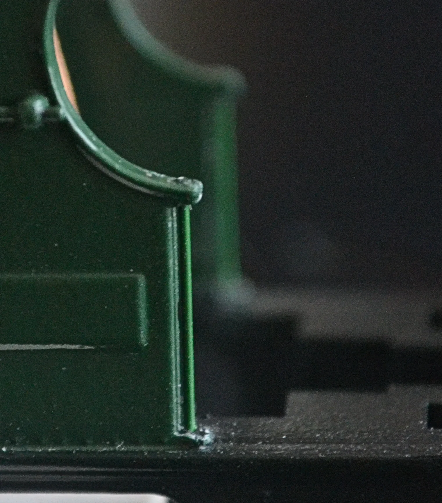
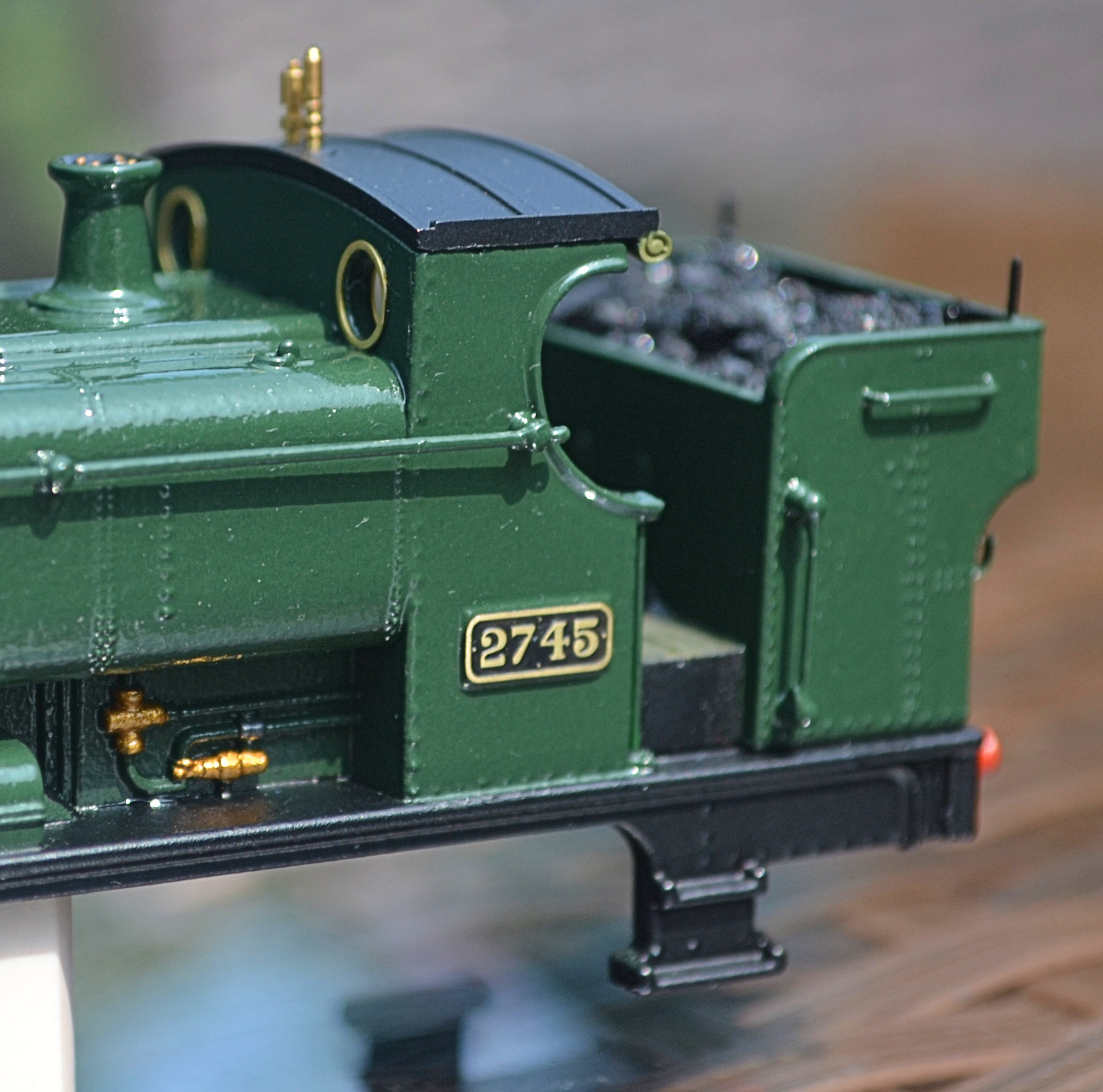
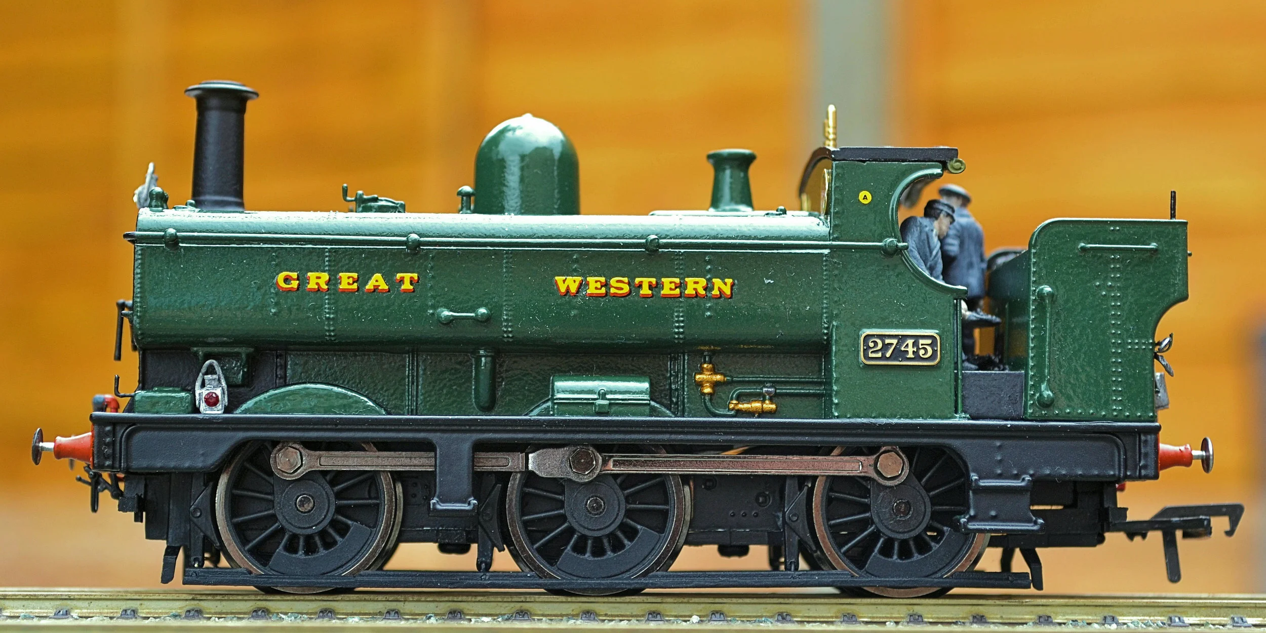
As the photos below show, the etched number plates have now been fitted to the cab-sides. I used Superglue Gel as it allowed a little time for adjustment. The glue was applied to the cab-side and the plates picked up and positioned on a cocktail stick tipped with blu-tak. The etched spectacle plates have also been applied to the cab - both inside and out - and held in place with Johnson's 'Klear'. Once fixed, a further coat of 'Klear' was brushed over them. The vertical cab handrails have been painted and the injectors have been detailed in brass and steel. A coupling has also been fitted to the front buffer-beam.

Whilst the spectacle plates improve the look of the cab front enormously, they highlight the fact that the cab is not glazed. After pondering this a little, I cut some windows and attached them in the frames with 'Klear'. To make the windows, I stood a 3mm tube on end on a thick, clear piece of perspex and drew around it with a fine felt pen. Then, using shears and files, I cut out two perspex disks and applied them as explained above. It looks difficult - it isn't though, and the whole operation took a hour. The improvement is considerable [even though the photos are rather poor...].

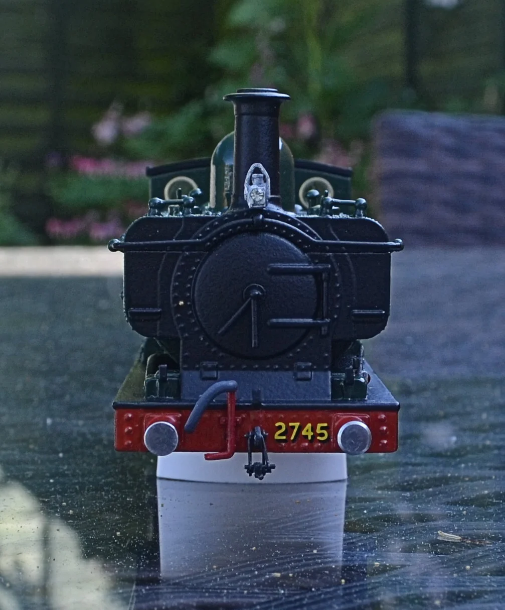
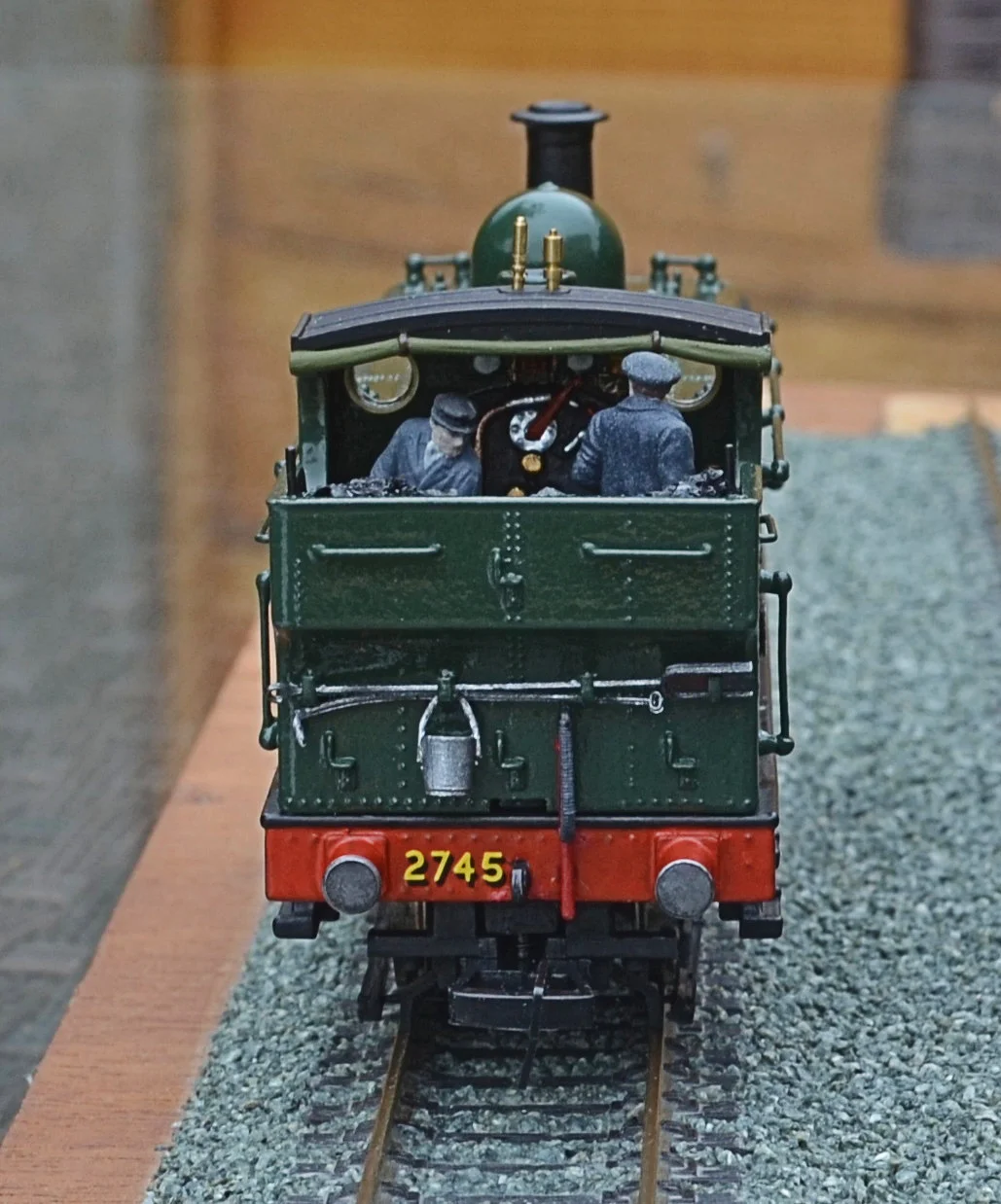
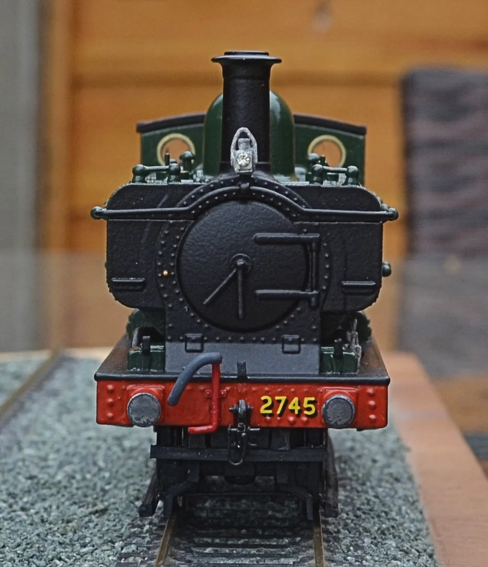
With tank-side lettering and buffer-beam numbering in place and the buffers fitted, the project is very nearly complete now. I just have to fix the crew into the cab/bunker unit, attach a dummy coupling hook and vacuum pipe to the rear buffer-beam, glue the bunker unit into place and the whole can then be reunited with the chassis. The front sand pipes will be put in place once the chassis and body have been reunited to prevent any fouling of the wheels. The lamp code is for a branch/stopping passenger or mixed train.


Pressfix lettering was used throughout and came out really nicely I thought, although this batch had a sticky gum residue which was difficult to remove from the body sides without damaging the lettering or the paintwork itself. I used Tesco's shower cleaner on an old hankie to clean it all up: it worked a treat, removing the gum residue without damaging anything. It's quite extraordinary what you discover in this hobby ! Once happy with the result, the body and buffer-beams had a final coat of 'Klear' to seal the transfers and so protect them from handling. The buffers are sprung and work nicely. The lamps and the bucket are white-metal castings from the 'Springside' range. They had their handles removed and replaced with thinner gauge wire to reduce the rather heavy look they came with as bought.
Two completely unexpected problems arose when I refitted the chassis. The first was that the body sat a good 2.5mm higher at the front than the back. A great deal of internal trimming and adjustment made no difference at all but the fault was eventually traced to some wiring which re-positioned itself every time the chassis was inserted into the body. Annoying, but now sorted.
The second was far more serious. Whilst planting the crew, I somehow managed to completely superglue a finger to the side of the bunker. This really was a problem. However, a lot of very gentle scraping with a new scalpel blade, some sanding with a 3600 finishing cloth and then a mass of Johnson's 'Klear' pretty mush disguised the mess. I know it's there, but it's not too obvious and will be missed by most. But never by me !
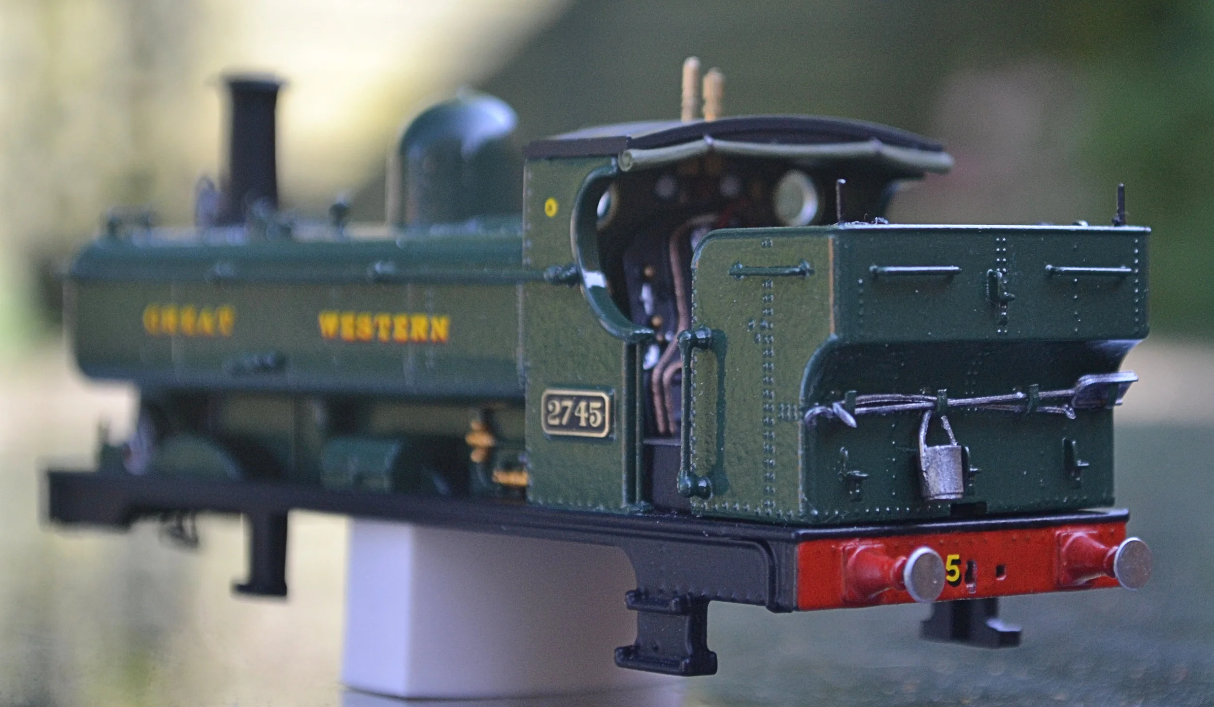
And the finished model...


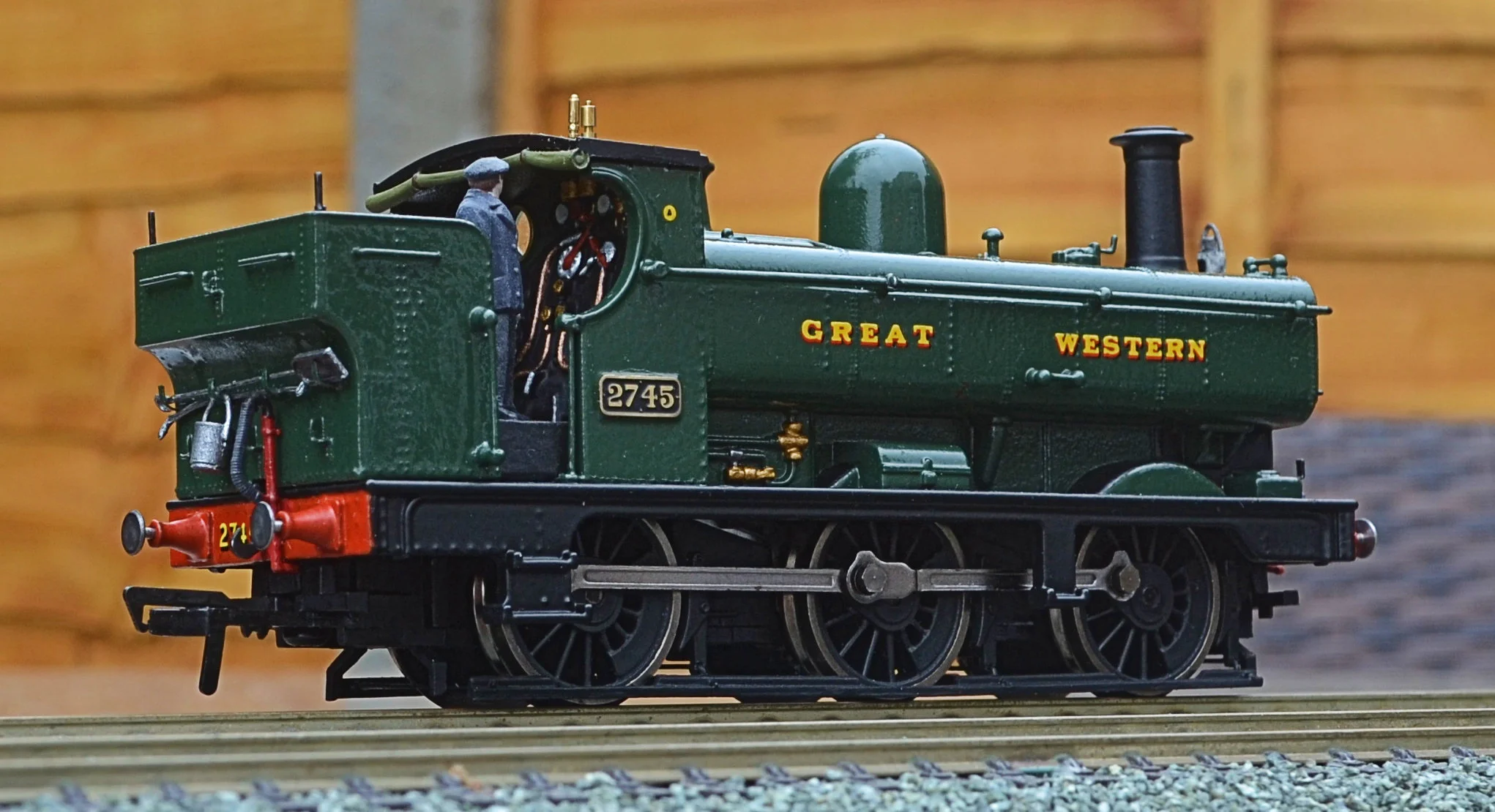
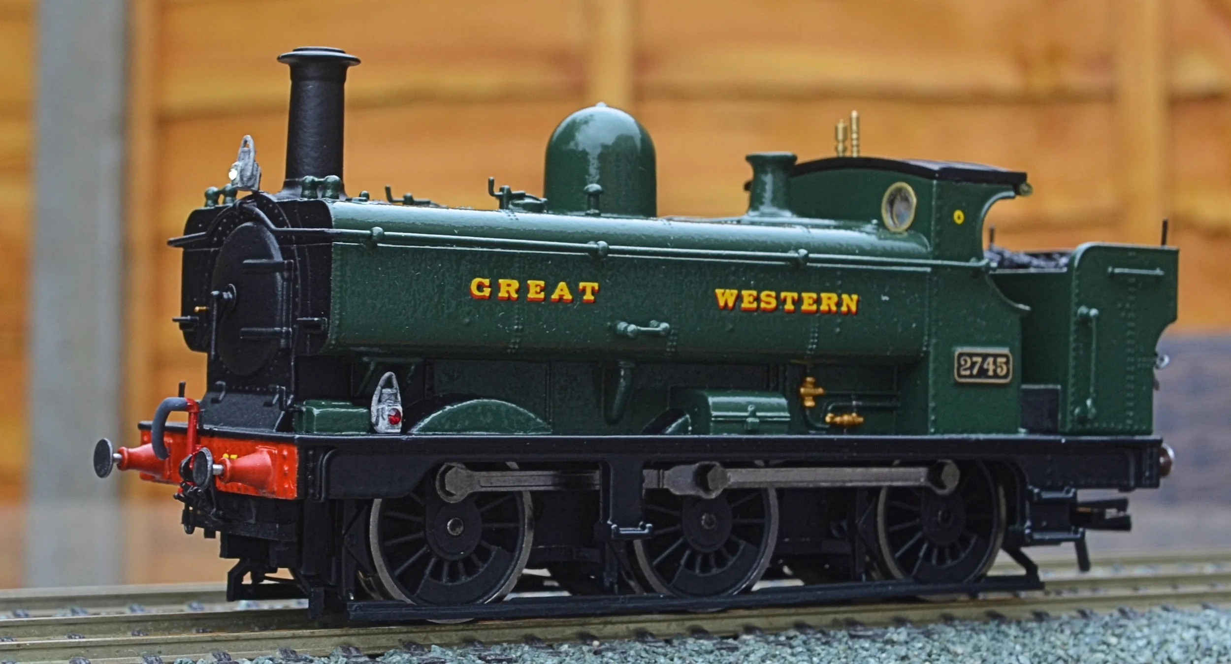
As a facelift exercise I think that this has been quite successful. Purists won't like it but it is a 100% improvement and well within the capability of every modeller. Certainly, 2745 will now see far more use than it would have otherwise and its future will see it pulling a rake of Ratio 4-wheel coaches that have been waiting for a dedicated steed for a while. It has also been a cheap exercise: apart from the cost of the donor model [bought five years ago for less than £50], all I had to purchase were paint, buffers and etched spectacle plates. All less than £15.The bits box took a pasting however!