- Hawksworth Dynamometer Coach -
Photo used with permission and thanks, courtesy of Coachbogie on RMWeb
In 1961, British Railways rebuilt a 1947 Hawksworth Corridor Third as Test Car No. 4, the replacement for the ex-Great Western Clerestory Dynamometer car, which was then sent off into preservation. Dynamometer cars are rarely modelled and only one, the LNER Clerestory Car, has made it in r-t-r production. The kit that this coach provides the basis for was manufactured by Mopok around 45 years ago and is a white-metal, acetate and wood construction with screen-printed sides which need to be attached during completion. The kit came with no instructions to speak of.
Surprisingly, colour photos of this one-off vehicle are really scarce. So, too, are good quality, well-focused b&w images. So building it without some instructions will be an interesting challenge!
I plan to use the underframe of the excellent Hornby Hawksworth Brake Composite as a general guide for the chassis, and the images provided by Comet for their Brake Third coach kit. Photos on the net will then, hopefully, indicate where some of the visible additional gear will be placed.
As stated, the kit is a mixture of wood, white-metal, plastic and acetate. Whoever owned it originally had made a start on the assembly but got no further than sticking the white-metal ends to the acetate tunnel that makes up the body shell. With some difficulty, I managed to separate the three parts for cleaning up successfully. This was fortunate, given the complicated doming that characterised the ends of Hawksworth coach roofs: impossible to recreate in card and I had no stomach whatsoever for carving them out of balsa or a plastic card laminate.
Various parts [buffers and those ends] will be replaced by bits from my bits-box: Mopak parts themselves actually, identical but unused and from heaven knows where.
When completed, the coach will run with a rake on Mk 1 coaches I have acquired over the years to run behind a Hymek or a Western.
Having cleaned up the floor and the acetate body shell, this is the starting point. It includes a compartment moulding and some other parts from my bits box.

The printed sides I put aside to keep them safe. But it quickly became clear that without the instructions, assembly would require some very careful thought. I started by cleaning up the replacement ends that I had, the originals being too unrecoverably covered in some sort of hard epoxy cement. My ends needed a lot of careful dressing to remove some heavy flash but, as the photo shows, cleaned up and painted, they came out well enough.


A dry fit of the floor, ends and body shell showed that the sides of the body shell had been cut too short [and were insufficiently deep] by the previous owner and so could not be glued fully to the floor sides when the time was ready.
Resolution: the edges of the floor were built up with strip wood so that the sides of the body could be securely attached in due course and each end of the floor had sections cut out with a fret saw so that one end could slot into the socket in one of the whitemetal ends and the other simply drop loosely into place, to be held with tape. These cuts are shown in the photo below, they are larger at one end so that the whole floor can drop out for removal when required. The second photo shows the floor with the strip wood attached.


The shell was then attached to each of the white-metal ends with contact adhesive - my least favourite glue - the floor inserted and the whole unit taped up for 24 hours. It should be OK when I next check. I may reinforce the joins carefully from the inside with epoxy, but will have to be very sparing or this will show through the door windows. It’s difficult to see how anything could develop from this flimsy construction at this stage…….

The good news was that the shell had held well to the ends and the unit is quite strong. I have drilled and inserted replacement white-metal ventilators after finding a side plan of a Hawksworth Third on-line. The vents are correctly off-set and in the right positions - but on the wrong side of the coach! I could kick myself for that stupid, fundamental error. I can match them up to their correct printed sides though, so no-one will notice. It doesn't matter, really. I have also stuck on a water tank top. There are two more covers to fit to the roof and the pipes for the water tank, I can then mask off the body and spray the roof black.

Now, the problem area.
You can see how the shell is attached to the ends: impact adhesive applied to the rebated inside edge of the end castings. This is where I have my first body problem. The measurements for the shell and the printed sides are incorrect, the shell is too short and the end doors on the side panels lie 50:50 across the rebates. Consequently, the joint and the adhesive are visible. There's absolutely nothing at all I can do about that but I know that I simply will not be able to live seeing the mess through the door windows either. The only solution will be to mask off the inside face of the sides and spray the door windows white. I thought about careful localised sanding to make them translucent, but the mess behind would still be visible. Frankly, only those who know the coach (and I didn't, before) would realise that it's a dodge. It'll be OK.
The other issue is a dent in one of the printed sides. It's a slight but visible crease and I cannot flatten it out. It looks that it may have happened when the previous owner either mishandled it or packed it away over a casting so that it could not lie flat. Again, I cannot remove it but am hoping that it won't be too jarringly obvious.
Apart from the ventilators fiasco, the body is essentially complete but undecorated. The coach was fitted with larger-than-normal coach buffers when converted in 1961 and I managed to find some to fit. The roof detail was difficult though, some conjecture was necessary to gauge the size of the three panels: their location is OK though. The smaller middle panel is representative only as there was raised detail (possibly a vent for the diesel generator?) that I couldn't see clearly enough from a photograph to copy.

A prominent feature of the Hawksworth coaches was the guttering that ran above the sides and Mopok appeared to have made no provision for this. Without it however, the nature of the overlaid side will be all too apparent because of the slight ridge along its top edge. This'll need more thought before the roof is sprayed - possibly very thin square micro-rod could be attached. A very straight line will be absolutely necessary, too. Tricky, but not impossible. The photo below shows the pipework for the water tank, the replacement buffers, the alarm gear and a corridor connector: all a bit messy but this will be fine once painted.

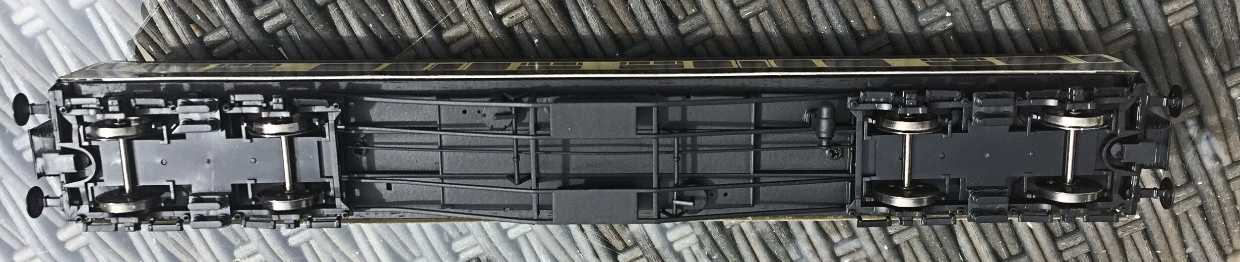
The entire underframe area has now had a complete rethink. The kit came with (correctly) four sets of truss rods, two with integrated sole bars. The four suffer from excessive and very thick flash and moulding pips. They are also extremely fragile and I doubt that they will hold out even if dressing them without braking them is possible. The kit bogie sideframes are correct(ish) but very heavily cast. I planned to use white-metal bogies of my own, then changed my mind to use correct Bachmann bogies. A further change of plan now means that the bogies from a Hornby Hawksworth Third will be used, together with the detail parts from that underframe. The Hornby truss-rodding is very fine and the brake gear excellent. The bogies are works of art. I'd have used the entire chassis had it not been to scale, and so too long and too wide for the kit's body shell and sides. The Hornby chassis has been fret-sawed into three parts, each of which have been further reduced in width and length. All of the detail parts have been removed without damage and the lot will be reassembled for attachment in due course. The original kit parts will not be wasted and will find use at some time in the future.
So, once completed, the only parts of the original kit which will remain are the body shell and sides, the floor and the various parts of the solebar! Adapting all of the replacement parts will not be without challenge (the running height for eg. will be trial and error initially), but that's the fun of it all.
Finally, Hornby Hawksworth Thirds are very expensive coaches. This scavenging is not the extravagance it seems however. I bought a crimson and cream coach three or four years ago quite cheaply with the intention of repainting it for GWR use. I was unhappy with the finish though and soon lost interest, it went into the bits box with the knowledge that it would, one day, be put to good use.
I have now managed to fix some guttering in place on the acetate shell, using .02" square section micro strip. In white, it looks just a little over scale but when sprayed matt black it'll be fine. The difference it makes is quite considerable, as the before and after dry-fit shows. This is also the first outing for the printed sides.


The next photo shows some additional 'padding' I have given to the lower side of the body shell to support the printed overlays. This was necessary to bulk out slightly the body shell as it bowed inwards and showed a pronounced curve. I used .01" plastic strip and it worked out well, providing support to the overlaid sides which has 99% eliminated the bowing. The roof and ends have also been sprayed matt black. I sprayed a couple of mm.below the guttering also to help hide any inconsistencies in fit later.

Next, the overlays were cut to size but you can see just how short the body shell itself was as the doors practically reach the very end of the body. It looks OK though and I'm perfectly happy with it. The guttering that I applied provided a really useful buffer against which to locate the overlays, ensuring that they would be in exactly the right location. The overlays attached well although the impact adhesive reacted very slightly with the black paint on the inside of one of the end door windows (I chose black instead of white in the end, it looked more credible). The body shell is also slightly longer at the top than the bottom, so some fiddley cutting was required, pretty much trial and error, shaving extremely thin slivers off with a new scalpel blade. But, all-in-all, a 98% success rate in terms of everything ending up where it should have! I have only posted a photo of one side but, already, the coach is beginning to look quite promising. Painting the inside of the end door windows black instead of white has paid off, too.

Not the most exciting photos below, but progress nevertheless.....
Both side overlays have now been attached and they line up quite nicely with the shortening not being too painfully obvious. The photo shows the interior of the coach. It is extremely visible from outside and a lot of detail needs to be added: three compartments at the toilet end, curtains on most of the windows, brass corridor rail, a misted toilet window and, somehow, equipment for the machinery/measuring device end. Lord knows what I'll put in there.
When the floor is inserted, there is almost no bowing of the long sides at all.

I've turned to the chassis now. The centre section of the underframe has been rebuilt and attached [screws] to the wooden floor. It went back together quite well and will look good once sprayed black. The mounting plates for the bogies will be stuck to each end once their precise position has been measured out. The bending in the truss rodding has been eliminated, also.

The underside of the chassis is now finished and can be seen, below. The three sub-units fitted nicely having been shortened and a spray of matt black standardised the finish, covering the wood and the plastic.
It wouldn't have been possible to have achieved this level of detail with the castings supplied with the kit.
On its wheels at last and looking recognisable. I have used 12mm disks instead of 14mm ones as the body stood just a little too high. When I can get to my other coaches (in the loft) I'll be able to see how it fares against a BR Mk1. In the meantime, it compares well in height with a Hornby Railroad coach.
The body awaits the kit’s adapted white-metal solebars (6 pieces, the very last things to be attached), steps, door handles and grab rails. And the interior of course....

These are two of the units I knocked-up for the instrument end of the coach. Thy have no real basis in reality, but a photograph I found showed banks of measurement equipment and they are based very loosely upon them.

The interior of the coach has now been now completed. The four compartments are scrap from an old Hornby coach. The blanked out window is a shower area (why did they have one?). That compartment also contained two toilets. The end compartment with a red lump in it contained a diesel powered generator for the electrical systems. I have no idea what it looked like and simply glued in an old coach dynamo casting with a belt at the pulley end.


The front two compartments are not accurately modelled. One should be a kitchen area (I think), the other a 'conference room', but I have also seen a plan for that compartment with seats in, so it has been left as it is. The light green lino floor at the business end has been simulated by a glued card strip. Unfortunately, the glue used to attach the furniture and equipment has marked it, but this cannot be seen from outside. All of the furniture has been sprayed gray to imitate metal Ministry furniture.
The lower half of the interior of the body shell has been coloured too. Because of limited space, neat painting was too tricky I found and I opted for an easy alternative and stuck in some fawn paper to simulate the Formica-type finish. It's actually OK.
Once the body shell has had its brass corridor hand rail attached and curtains hung, the chassis / floor area can be inserted. All that will be left to do then will be to paint and attach the various solebar sections and add the door handles and grab irons.
Best laid plans! With the floor inserted and secure, I found that the white-metal solebars were not really usable unfortunately: they were simply too irregular and poorly cast. I used some plastic channel of the same size instead, it looks quite convincing and very much easier to fit than six separate sections of white-metal would have been.
This build is now finished. The coach required a little touching up in matt black here and there (particularly the bottom edges of the screen-printed sides), some hangers to attach to the corridor connectors have been added, some steps were attached to the solebars under the doors, some tiny steps attached to the ends of the coach and some frame dirt applied to colour slightly the corridor connector bellows. Door handles and grab irons were also added to the flush sides, creating a little relief.
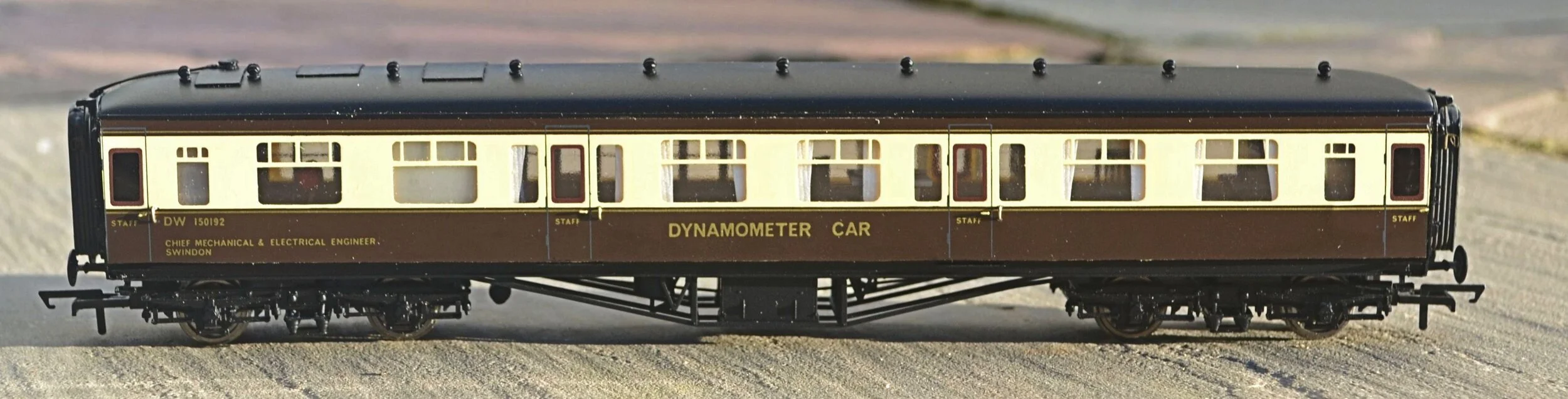

This has been a satisfying build, providing an interesting, unique coach which could only be acquired this way. It’s hard to believe that the coach above originated from [some of] this pile of parts….!
