- An Improbable Six-Wheeler and Other Clerestory Diversions -
by Tony Richards
I started building some K's white-metal 4 wheel coaches a while back [the build can be found here] and whilst the project has not been abandoned, it has rather been pushed towards the back-burner whilst I've got on with other things. In fact, the last two or three months has seen quite a lot of activity and a number of other builds distracted me from the 4 wheel task.
No matter. They will be finished but they have now become part of a larger project: a vintage coach rake including a K's Tri-Composite 6 wheeler and three or four other coaches. The rake will ultimately be hauled by a re-chassied GEM GWR 0-6-2 tank. This is a longer-term project.
So, in light of the above, I indulged in my favourite form of modelling and undertook some experimental surgery today to quickly produce this:
For some time, I'd been waiting for some sensibly-priced Triang Clerestories to become available on eBay. The first to come along was this [£7 and boxed]:
....but it was really too good to cut up so it has been saved until I find some replacement Dean bogies and better ventilators for it. It'll then go into the rake. What I did cut up was a slightly less mint Brake that came with a Third in blood and custard [the pair £11]. But what's it going to become ? I leave you with a final image as a clue. Believe me, improving the following is going to be an absolute mother of a task, but we'll get there.....
The Idea........
The GWR absorbed a huge number of obsolete and often decrepit coaching stock after the First Grouping in 1922-23. Much of this was scrapped immediately, but some remained in revenue for decades, running with little more than a change of livery and limited maintenance. These coaches often ended up in Workmens' trains. The GWR never built a 6-wheel Clerestory Brake Composite of its own, but who's to say that one was not inherited from one of its minor constituents in the early 20's ? That's the excuse for this build anyway.
I wasn't holding out high hopes for this project however as it was very much an experiment: it seems to have progressed reasonably so far though, with the usual commitments to compromise.
This is a risky stage however, things always look better before they are primed, when all sorts of flaws flop out of the woodwork. Anyway.....
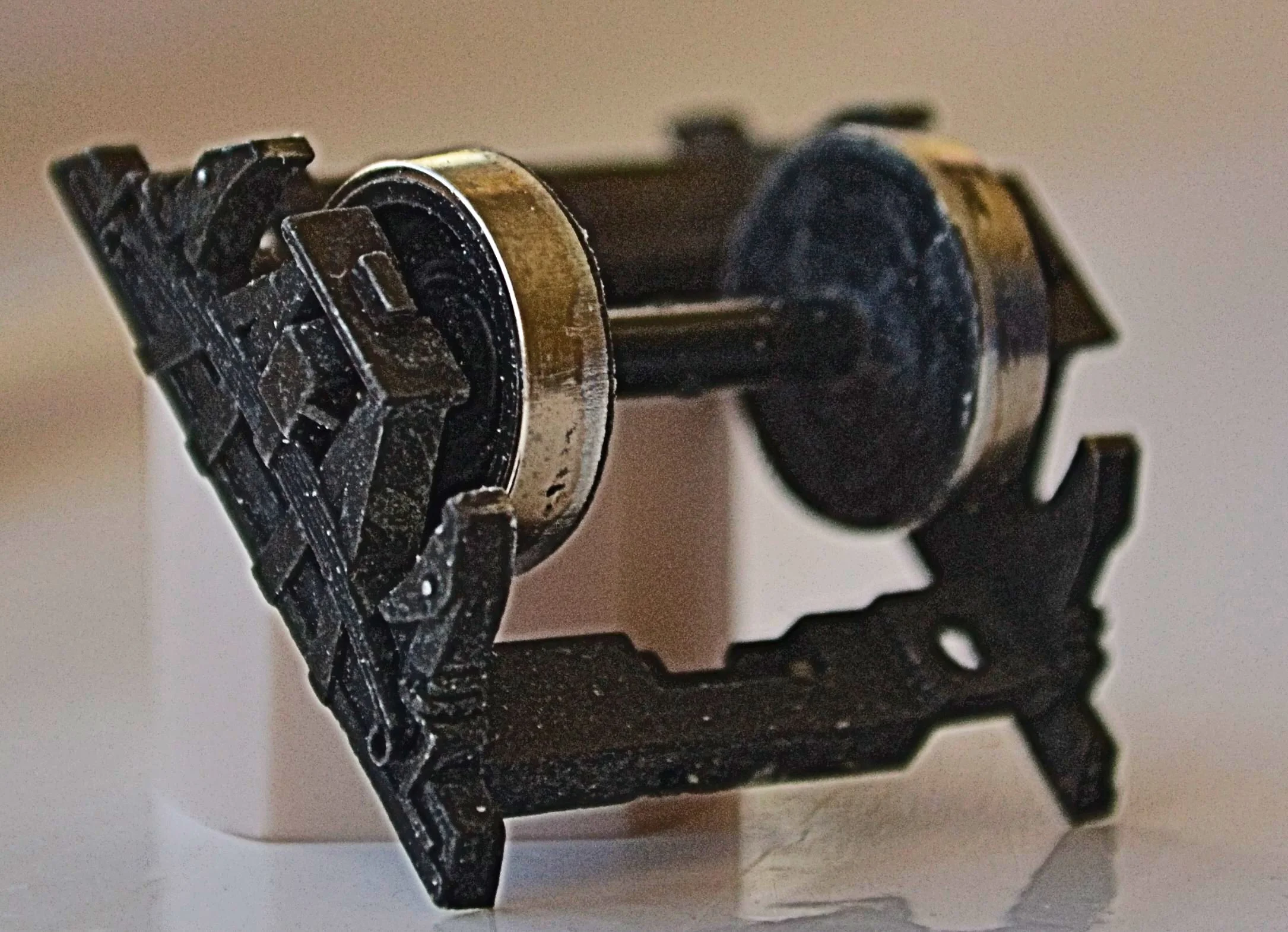
The chassis was the first to receive attention. Now, for those unacquainted with the [very] old Hornby 6-wheel chassis, it was fine in its day, with an ingenious design that allowed it to travel through the most impossible radii without derailing. The first photo shows how this arrangement worked. By today's standards it is ridiculously crude but that wasn't the reason for adapting it. As built, the chassis would not allow for the fitting of footboards because the centre axle-unit needs to move radially through even the slightest curve. This movement is actuated by rods attached to swivelling couplings. I wanted footboards, so the mechanism had to go.
I cut away the couplings, removed the articulating rods and pulled out the centre axle-unit to produce this [photo taken after footboards were fitted]:
The easiest way to remove the couplings and their brass fittings is to use a Xuron cutter. The centre axle-unit then had its wheel removed and the flanges filed down so that the wheels would rest flat on the rail top creating, effectively, a 4 wheel chassis. This sounds crude but it works well in practice and is virtually invisible from normal viewing distance. I retained, with some regret, the original Hornby wheels. Although plastic they are at least metal tyred but replacing them would be difficult because the axle-units are cast and inflexible, preventing scale wheels from being 'sprung' into brass bearings. Next photo shows the flange-less wheels. This was a big compromise that I'd rather have avoided: if the axle-units were to be retained it was inevitable however.
And another look at the foot-boards. The lower ones will receive hangers in due course.
The sole bars were cut from the bottom of the body, with a razor saw, before the two halves were cleaned up and glued together. Plastic strips were glued inside first to ensure a good alignment and the whole was then glued up, pressed against a steel rule to keep everything square. Not a bad join really, given that the units were cut by eye. Some Squadron putty will be applied later to fill the cracks and disguise the joints. It should be 95% successful.
Finally, the roof was measured out and cut up and the photos below show a dry fit at this stage. It will also need some putty filler but should come through well.
Boy Scouts and other keen-eyed observers will notice that there is one window too many in each side. I thought about painting the errant windows white, to represent a toilet compartment. I've decided to leave it as it is however as most will never notice it. This was an inevitable consequence of using the Hornby chassis, which dictated the length of the body.
At Least Several Shades of Grey [but don't get too excited].........
With filler applied to the joins, the body was left to cure over-night and then sanded flush prior to an initial flash of primer. The first result is quite good and I was particularly pleased with the roof [compare above and below]: some Milliput epoxy putty will be applied later, thinned down with a wet paint brush and that should be sufficient to fill the remaining seams prior to a final coat of primer.
In the meantime, hangers are still needed for those foot-boards.......
Putting the body aside for a while I carried on with the chassis. This is a labour of considerable optimism but probably one which is becoming unrealistic.........
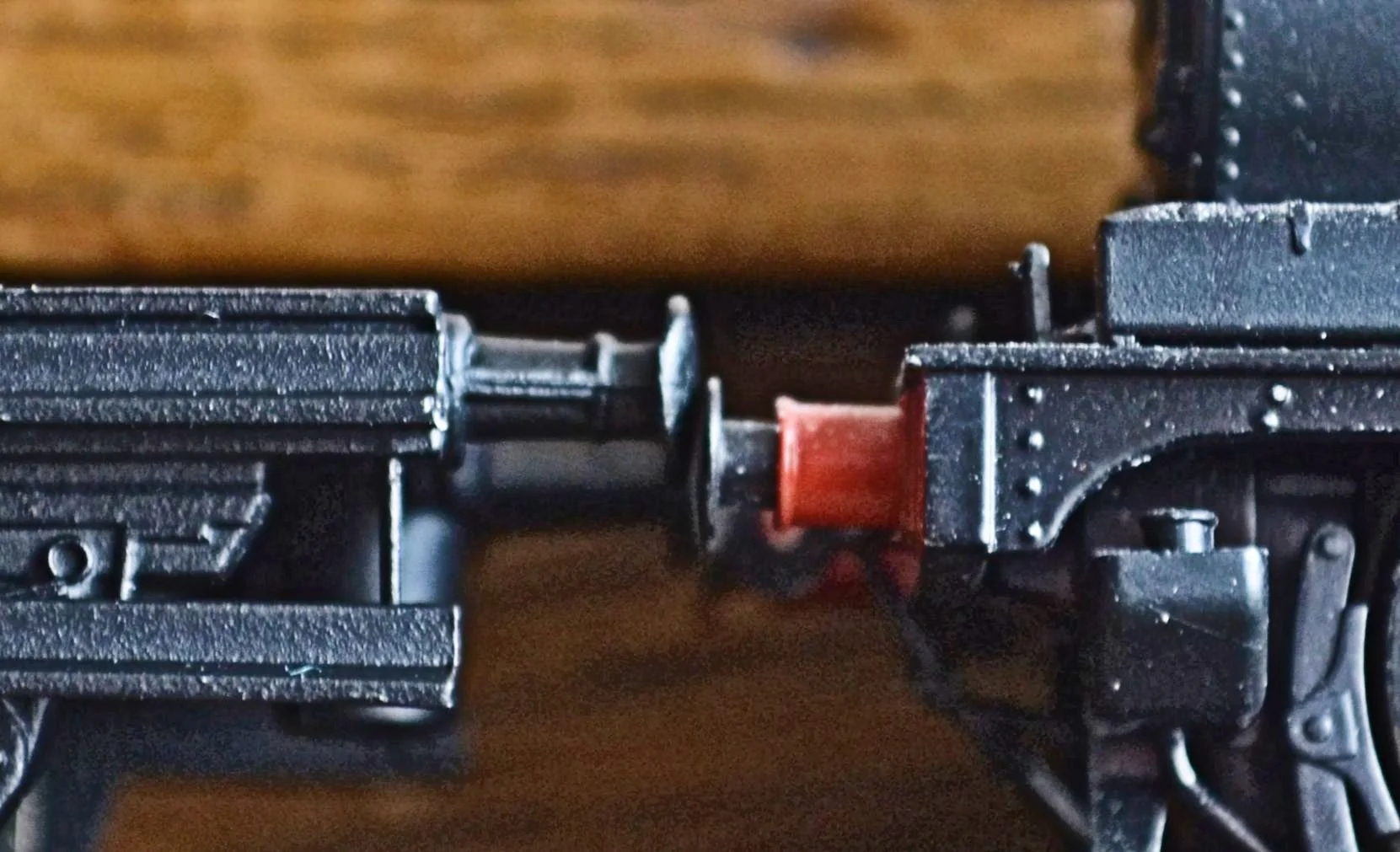
Having attached the foot-board hangers and cleaned up some moulding flash, I primed and painted the chassis for a test run. With the original wheels inserted, it ran well, with the flangeless centre axle sitting atop the rail head and rotating properly. Obviously nowhere near as free-running as modern stock, the chassis nevertheless rolled without too much drag and so was acceptable from that perspective.
Two issues became apparent however. The ride height was significantly out and, consequently, the chassis sat too high. The next photo compares the buffer height with an r-t-r tank engine. This was unacceptable. Secondly, the entire centre axle unit rocked back and forth whilst in motion and so could not be allowed to simply float on the clip that retained the axle. Some form of packing-out would be necessary to fix the unit at exactly the right height.
The overall ride-height issue would have to be solved through a little surgery as smaller wheels were not an option. This meant completely dismantling the chassis but that was unavoidable. The next photo shows how remedial work was to be undertaken: note the two small mouldings at each end of the top of the axle unit. These were plastic, part of the upper chassis moulding and they had to go to allow the axle-units to sit directly, flush, under the upper chassis moulding. The following photo shows them cut away from one end and at the other end remaining in place for comparison / identification.
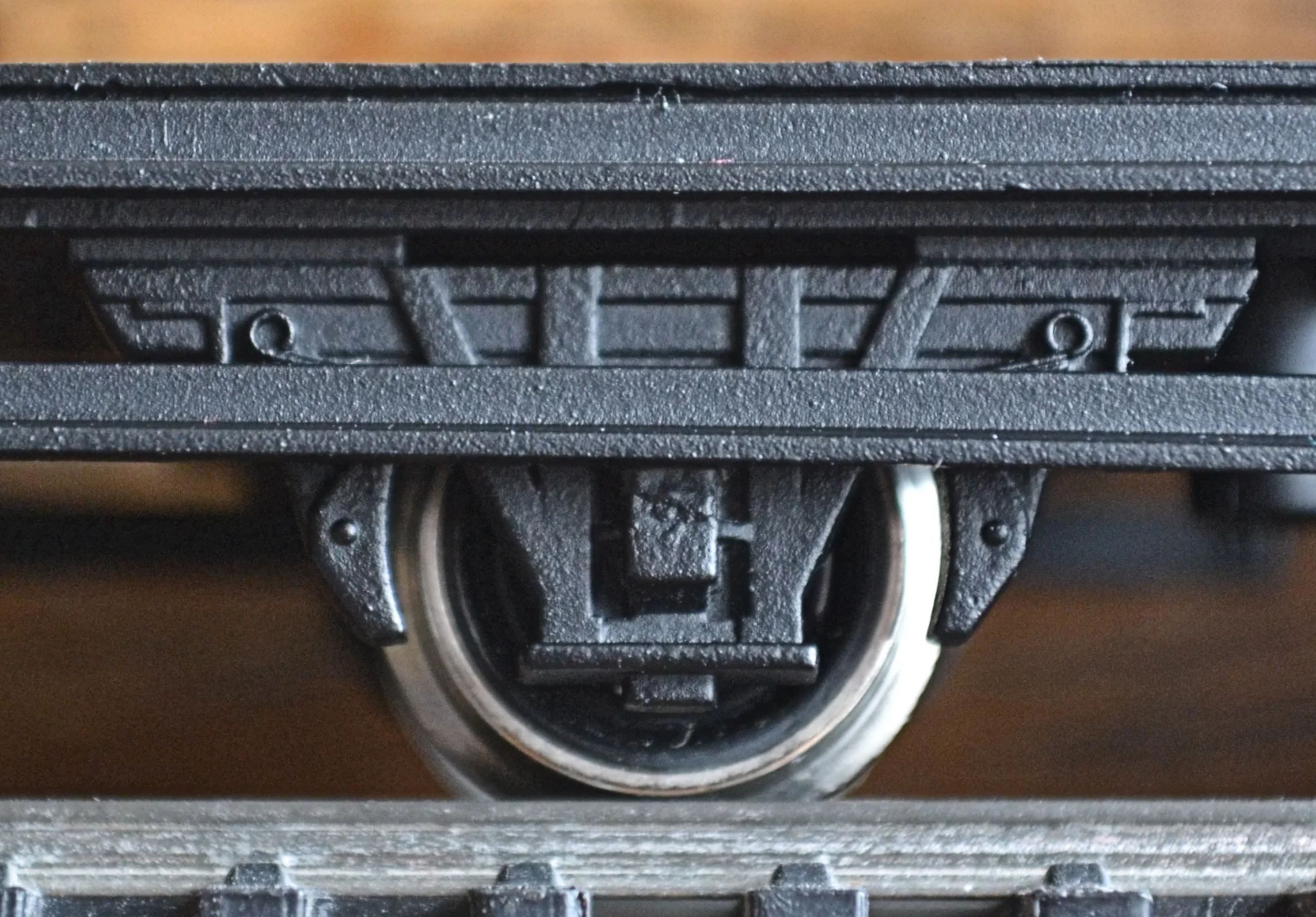
The next photo shows the improved ride-height. A drop of about 1.5mm was achieved and whilst not perfect by any means, it is cosmetically an improvement at least. I'd rather a lower fit frankly but it's difficult to see how this could be achieved given the construction of the chassis. I'll live with it, for the time being........
The next photo shows the completed and repainted chassis back on the rails, with the body a loose fit. Tie rods will be fitted to the W-irons in due course and the wheel edges painted to dull the nickel plate. It wasn't necessary to pack out the centre axle-unit in the end as it could now be glued directly under the chassis, like its fore and aft colleagues. It will need painting black though. Some more filler will be applied to the joins, too.
That Inevitable Diversion
So many other things have got in the way of modelling over the past few weeks but I have managed to make some progress with the 6-wheeler and also start and nearly finish a significant upgrade to an old Triang bogie Clerestory Brake [the GWR-liveried model shown towards the beginning of this thread].
The 6-wheeler now awaits lettering before it is varnished, glazed, has internal partition walls and couplings fitted, the roof weathered and the body reunited with its chassis. In short, it is nearly done. I'm becoming anxious about the ride height again however. I wish I could solve that one but smaller wheels weren't an option and the metal chassis could not be reduced further. It may have to run alone if the K's white-metal coaches it was built to run with are much lower. We'll see. In the meantime......
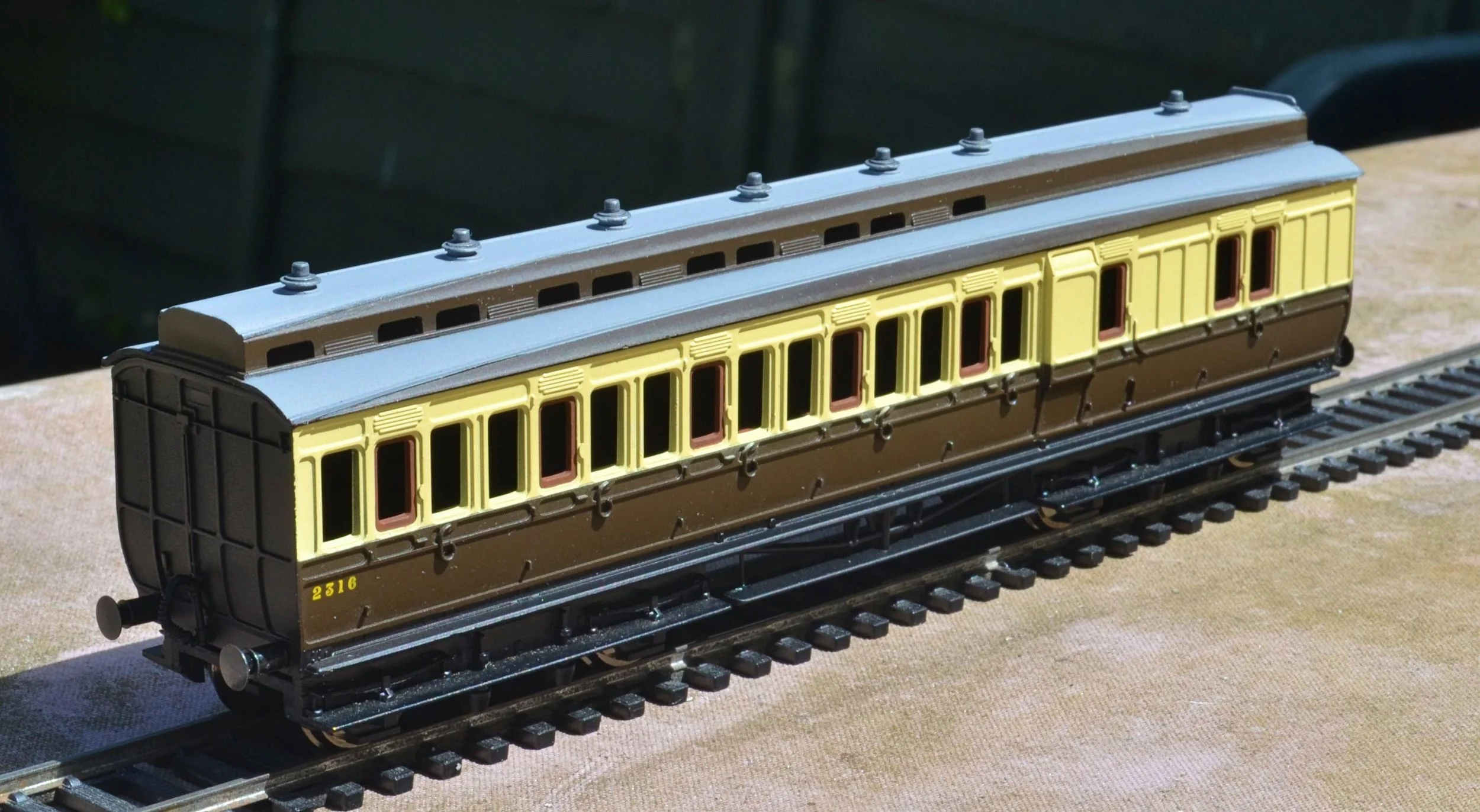
The old Triang Clerestory has been transformed I think through the addition of Hornby Dean bogies and truss-rods / queen posts and underframe detail from one of the later Hornby corridor Clerestories. An expensive exercise you might think, one that requires the sacrifice of the newer Clerestory coach unless, like me, you acquire three for £22 via eBay and mostly recover your costs by selling the other two for a tenner each. The coach awaits lettering, couplings and varnishing before flush glazing is applied, compartment partitions added and the roof weathered. It has been fitted with sprung buffers and more realistic roof ventilators. The drop-lights have been picked out in faded mahogany. If you want variety, you jolly well have to go and build it.......
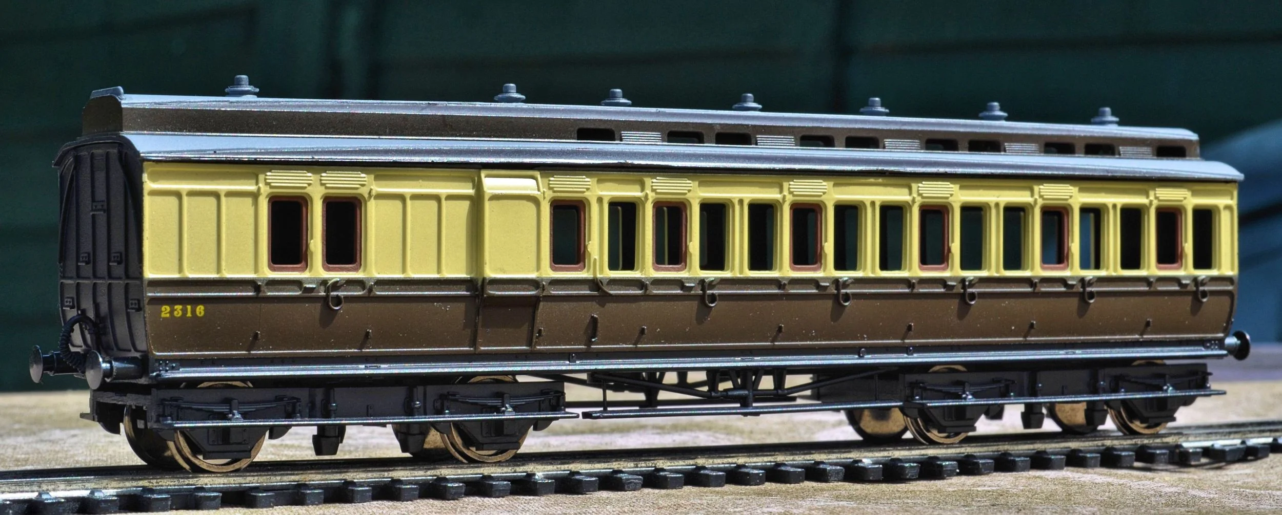
Both the 6-wheeler and the bogie Clerestory will be lettered in the 1927-1934 style.
A While Later..........
The Triang Clerestory is all but complete now and just awaits insertion of compartment partitions and some glazing for the clerestory windows. I used Finecast flush-glazing for this coach: it's not perfect but no where near as prismatic as the lower enlarged photo shows. And at less that £3 a coach it's a no-brainer !
If I can source some more Dean bogies, I will do another one later. It's worth the effort I think.
And the 6-wheeler ? Back to the workshop I'm afraid. I just couldn't cope with the height of the chassis and the model towers above its compatriots. I am going to scratch-build a replacement chassis using the original wheelsets. It may work, it may not. It's worth a bash though. After all, it's a hobby, not a race.....
I had no option really. I spent hours just staring at the old chassis before I concluded that it just couldn't be made to run at the correct height. Scratch-building was the only answer really as I do want to complete this build.
Building chassis with plastic card, especially when [as in this case] additional plastic and metal components have to be attached, is always a little fraught and there is an almost inevitable risk of warping: solvent-based adhesives and super-glue set up all sorts of tensions, particularly when applied to only one side. In this case however, the chassis will be, in effect, a sub-frame which will be firmly attached to the solid floor of the coach body, so any risk of twisting will be minimised.
This is where we are right now. Running on its own it would get away with it, but it's going to be part of a rake of six coaches, so there has to be some change.
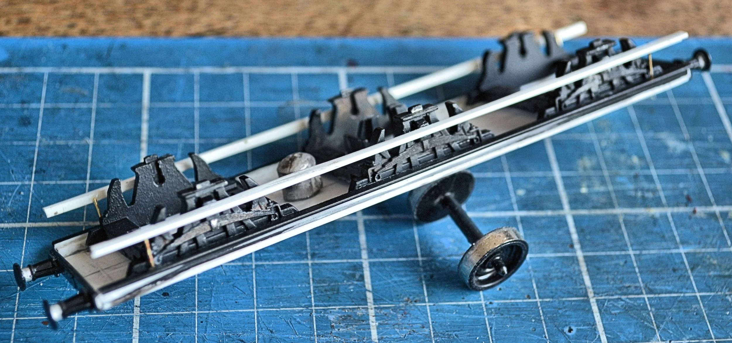
The new chassis plate is made from 1mm plastic card cut to 3cm x 12cm. It is deliberately shorter than the coach body to allow for the fitting of buffer beams - there's about 1.5mm to play with, quite enough given that each beam will be ever so marginally proud.
Once dressed to remove burrs, a lengthways centre line was drawn the chassis plate to aid fitting the w-iron/axle sets. The sets measure in width at 2.7cm and a set of further lines was then drawn on the plate, each 1.35cms to the left and right of the centre line. These lines mark the outer extremities of the axle sets.
Two lines were then drawn across the width of the chassis plate at 2cms from each end with a third exactly in the middle. These mark out the centre points for each of the three axle sets. The photograph below illustrates this. Measured and marked out carefully there should be no margin for poor or uneven running.
The axle-sets themselves cannot be glued directly onto the underside of the chassis plate as the flanges will foul. Consequently, 3cm lengths of 1mmx2mm plastic strip were glued to the tops of the axle-set castings and the whole, when then glued to the underside of the plate, provides about .5mm clearance. It doesn't sound a lot but it is sufficient. See the photo below, although it should all be quite self-explanatory.
All three sets were treated in the way described and each then carefully glued in place. Start with the two outer axle-sets first. Line them carefully by eye and then adjust them against the edge of a steel rule to ensure that they are snugly on the line. The middle set can then be easily applied by resting a rule against the outer two sets and butting the middle one against it. In this way, even if one of the outer sets is very marginally out of true, all three will nevertheless be in a straight line.
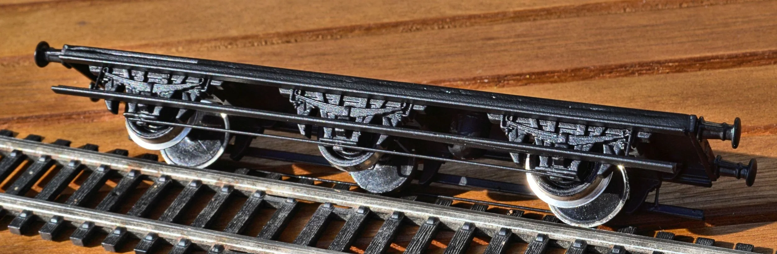
The next photo shows a comparative height shot. With just the outer wheels fitted, the 6-wheeler is now more-or-less at the same height as the bogie Clerestory. A satisfactory result. It would have been possible to have glued the axle-sets directly onto the underside of the coach body. I did think about that but reckoned - correctly - that the finished product might then be too low. It's worth comparing this photo with the one in my last posting to see how much height has been lost.
The assembly is still extremely flimsy at this stage. Tie-bars and foot-boards will add considerable longitudinal strength but it will only become really solid when it is attached to the coach body.
As can be seen in the photograph, the w-irons stand proud on the axle-set mouldings and this makes it difficult to fit the foot-boards as there is little level surface to glue them to. Consequently, I packed out either side of the w-irons with 1mmx2mm strip and was then able to glue the foot-boards to the strip. The photos below show first where the packing-out was placed and then the foot-boards in place. I reused the foot-boards from the original chassis: no point in wasting them. Obviously, everything will look rather neater when it has all been sprayed black.


The whole unit is also much more rigid now, which will make fitting the tie-bars a lot easier. I have yet to decide whether to fit lower foot-boards. I have also dug out from the bits-box some wagon buffer beams to adapt for the coach. I'll explain the odd-shaped moulding in the inside-middle of the centre axle-set another time.
Buffer beams are easily scratched up out of plastic card although I used some old Ratio wagon beams from my bits box and, with some filing and packing, they fitted well. After attaching them I realised that they were fairly shallow however, too shallow for any of my spare buffers as their shanks were all too wide. I settled for the buffers from the original chassis in the end - a really fiddley job to remove as they have to be cut with a razor saw from well behind and then their backs carefully filed and sanded flat. Only in this way can the shanks and their webbing be retained entirely. When glued in place they looked fine: this sort of modelling is all about credible compromise.
I decided to fit lower foot-boards too as they were such a feature on the originals. I had to cut down some 'T'-shaped strip to produce a narrow 'L' section for this however as the upper boards would have been well out of gauge if they were fitted across the axle-boxes. Brass wire hangers were glued at each end. The next two photos show pre-primer progress.

You'll see a rudimentary vacuum cylinder fitted. There won't be any more underframe detail added. The next shot shows the chassis in primer, with tie-bars now in place.
The next two photos show the chassis after it has been sprayed matt black. The second shot explains the odd-shaped moulding in the inside-middle of the centre axle-set: it's there simply to retain the centre wheel set which developed an annoying habit of dropping out.

The final two photos show the six-wheeler with loosely-mounted body [I can get on with painting the ends, lettering and glazing and weathering the roof now that everything works properly] and a comparative height shot again. Check out the positions of the buffers between the two coaches: perfect. Scratch-building a second chassis was a bit of a faff, but it was well worth it in the end.


Endgame........
Couplings added and ready to roll.

Finally fixing the body to the chassis was more difficult than I had imagined as there were no fixing points and everything had to be lined up by eye. In the end I used epoxy resin, mixed to go off quickly. The coach runs very smoothly too, with no wobbling. Next up, after the K's 4-wheelers have been finished, will be a 4 wheel Passenger Brake Van. Just need to source one more Clerestory Brake body............